Hello everybody,
Over the past week, I have been designing a mounting bracket for some stepper motors that I plan on using for my final project: a robot that will automatically put out a fire. In doing this, I used reference imagery to design the bracket in Onshape, and have since printed the bracket and mounted the motor to it. Since I documented the process of making this item, I wanted to share the process I used, and do so in such a way that anybody would be able to replicate the general process should they choose to. Anyways, let’s go ahead and get started:
Selecting and Importing a Reference Image:
If one were to look up “stepper motor dimensions” or “stepper motor schematic” in a search engine, one would find a vast multitude of images, most of which would be unusable for the purpose of being a reference image. In this case, it is useful to know the exact part number, so that you can find the exact image you would need. For our stepper motors, the part number is 28BYJ-48. If someone were to look up this number instead, using something like “28BYJ-48 dimensions,” they would find a page with specific dimensions they would need. For my bracket, I used the image given by cookie robotics:

https://cookierobotics.com/042/
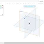
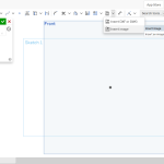
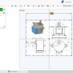
Then, having selected my image, I opened up a new document in Onshape and started a new sketch. Selecting a side, I opened the sketch and imported the image as shown in the pictures below:
Scaling the Image and Designing a Part:
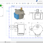
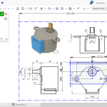
Now, with the image uploaded, I chose one of the many dimensions and created a line matching in length to the dimension stated. From here, I shrank the image until the dimensions approached an approximate sameness.
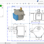
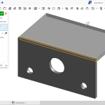
Then, I created the face of my bracket using the image as a reference; resulting in the first image below. Extruding this sketch to 2 mm, I then created the back panel using the same imagery. With the final extrusion completed, and some minor details tweaked, I now had a finished design that I could upload to a slicer and work on getting printed.
Printing the Bracket:
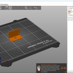
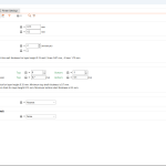
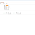
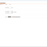
So, after downloading the file for the part, I imported the file into a file slicer to prepare a file for printing. The slicer program that I used was Prusa Slicer, although this would be different for whatever brand printer a person is using. Uploading the part file, I went into the slicer settings and changed the printer to be used and the material to PLA (also printer-specific). All of the settings, in case someone has a Prusa printer, are shown in the images below:
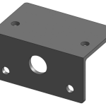
The Final Product:
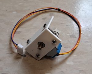
So, with all of that work done and the sliced gcode file obtained, I was able to move the file over to the Original Prusa I3 MK3S+ and begin printing. The print process took about one hour and twenty minutes, and by the end, I had a great-looking, personalized motor mount for my stepper motor. The motor fit into the mount without any issues and now I can move forward with my final project and all the minor projects along the way!
Recent Comments