Hello everybody,
At the beginning of the fall 2022 semester, all of the students in section 70 of ENGR 199 were given a problem that we would be working on over the semester to solve. The problem that we were given was “how to put out a flame that happens to be located at the end of a maze, or rather around a series of corners, using a robot built on an Arduino Uno.” As anyone reading this may have noticed, I have created a series of posts throughout the semester showing my progress on various parts of the robot. My partner, another student in this class, was doing likewise, and as a result, we have been able to put our parts together to create the body of our robot. You can feel free to check out his portfolio site here: Bruce’s ENGR Portfolio.
For this blog post, however, I will be detailing more on the process that I followed as the electrical engineer, and how I contributed to the project. To start, I will note my initial thoughts about how we might have gone about reaching our set end goal of extinguishing the flame.
Initial Thoughts:
At first, I was rather confused about exactly how the robot would make it through the maze, having had no experience in coding or robot design previously. However, I was able to think about how I would have liked the robot to make its way through the maze. Essentially, I was looking to set up the code, once I learned how in such a way that the robot would be able to make it through any single-path maze. Luckily, and with the effort put in throughout the semester, I was able to blend all of the codes we learned into one amalgamation of code that can fulfill this initial goal.
The Process:
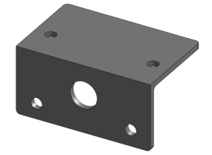
As we moved throughout our course, we built and developed several items and codes that we would put together for this final. The first of these items was the motor bracket that was developed and built from the end of October into the beginning of November. Take a look at that post if you would like to know more details on the process that I followed, but in short, I effectively used a reference image to design a bracket that I then finalized and printed using a Prusa Original Mk.3.

Then, we began working on understanding the theory behind ultrasonic sensors. Using this knowledge, we worked to build a code that would utilize an ultrasonic sensor to control a servo; using Arduino’s servo library (Servo.h), and acting as something akin to a sliding door with motion detection (similar to those in supermarkets and such). I originally built this code so that once an object came within a certain range, the servo would “open” to 180 degrees, then return to 0 degrees after a set time. To correct this for improved realism, I ended up changing the code to make the servo stay at 180 degrees until the object leaves the detection range. The final code for this piece is shown below and the post for this can be found here.
#include <Servo.h>

int inches = 0;

int cm = 0;

Servo servo_9;

long readUltrasonicDistance(int triggerPin, int echoPin)
{
  pinMode(triggerPin, OUTPUT);  // Clear the trigger
  digitalWrite(triggerPin, LOW);
  delayMicroseconds(2);
  // Sets the trigger pin to HIGH state for 10 microseconds
  digitalWrite(triggerPin, HIGH);
  delayMicroseconds(10);
  digitalWrite(triggerPin, LOW);
  pinMode(echoPin, INPUT);
  // Reads the echo pin, and returns the sound wave travel time in microseconds
  return pulseIn(echoPin, HIGH);
}

void setup()
{
  Serial.begin(9600);
  servo_9.attach(9);
}

void loop()
{
   // measure the ping time in cm
   int delaytime = readUltrasonicDistance(7, 8);
  cm = 0.01723 * delaytime;
  // convert to inches by dividing by 2.54
  inches = (cm / 2.54);
  Serial.print(delaytime);
  Serial.print("uS, ");
  Serial.print(inches);
  Serial.print("in, ");
  Serial.print(cm);
  Serial.println("cm");
  delay(100); // Wait for 100 millisecond(s)

  if(inches < 10){
  servo_9.write(180);
  }//end if

  else{
  servo_9.write(0);
  }//end else
}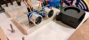
The next item that we then began to work on was the flame sensor, and by the association of our use, relays. Effectively, we learned how a flame sensor worked, as well as how relays work to connect external objects (a fan in our case). After we obtained a practical knowledge of these functions, we then learned and worked on making a code that would allow the flame sensor to activate the fan, through the relay, once the sensor detected a high or low enough value. The final code that I ended up with for this assignment was as follows:
void setup() {
  pinMode(13, OUTPUT);
  Serial.begin(9600);
}

void loop() {
  int val = analogRead(A0);
  Serial.println(val);
  delay(1000);
  if(val >=600){
    digitalWrite(13,HIGH);
  }
  else{
    digitalWrite(13,LOW);
  }
}
As with the other items, you can feel free to look further into my post regarding the flame sensor here.
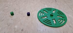
Finally, the last pieces that my partner and I put together were the wheels for the robot, as shown in my most recent post to date. The process that I followed for this was that I first made the wheel’s hub, then adjusted the dimensions so that the hub would fit more tightly on the motor. After increasing and shrinking the dimensions over the course of a couple of iterations, I added some decorative elements and finally printed out my wheel, attaching it to my motor on the robot. I learned, however, that in the process of removing and replacing the wheel as Bruce assembled the robot, the hub of the wheel became increasingly less snug. As a result, I decided to shrink the dimensions by roughly 0.1 millimeters, printing a new wheel that fit much more snugly than its predecessor.
Writing the Robot’s Code:
Thus, with all of the parts of the robot created, and most of the major code written, Bruce and I were able to assemble the robot in its full glory. After assembling all of the electrical components and connecting them over two different breadboards, I went ahead and began to assemble the code for the robot to function as I had planned it to.
Essentially, this meant that I connected all of the code for the sensors, as well as some code for the stepper motors that we used (taught at a point later in the semester), and began to test and troubleshoot the code. In doing this, I found that my code had a number of issues and errors that I needed to resolve since the robot was acting semi-functional but had no motor movement.
- The first of these that I tackled were the missing semicolons in the few places I had forgotten to place them.
- After that, I added a few lines of Serial.print(“~~~”) into the code so that I could determine how far the code was making it.
- Using this information, I delved into the order in which I had made the code and found that the order itself was the thing causing many of the problems to occur. As such, I relocated some of the integers to be within their different functions respectively, and then replaced integer values where necessary.
- Testing the robot once more, I found that the motors and the fan were still not activating as they should have.
- With that in mind, I reinspected my wiring and found that I have placed my wiring backward for the motors and that I needed to change the relay wiring from NO (Normally Open) to NC (Normally Closed).
Making these changes, I tested the robot once more, and all of the code was now appearing to be functional. Now it would be time to actually put the robot to the test and to make value adjustments to fine-tune movements and distances in the code.
The Finished Robot:
After making some changes to the code as listed above, I was able to transfer the code over to the Arduino and test the robot in action. In this testing, the robot encountered a few problems, such as the right turn not being fully 90 degrees, the distance detection being too short or too long and causing the robot to collide, and power supply problems wherein the batteries we were using began to fail. After hammering out all of these problems, the final code that we ended up with is as follows:
#include <Stepper.h>

int inches = 0;
int cm = 0;
const int stepsPerRevolution = 2038;

Stepper LeftStepper(stepsPerRevolution, 2, 4, 3, 5);
Stepper RightStepper(stepsPerRevolution, 8, 10, 9, 11);

long readUltrasonicDistance(int triggerPin, int echoPin)
{
  pinMode(triggerPin, OUTPUT);  // Clear the trigger
  digitalWrite(triggerPin, LOW);
  delayMicroseconds(2);
  // Sets the trigger pin to HIGH state for 10 microseconds
  digitalWrite(triggerPin, HIGH);
  delayMicroseconds(10);
  digitalWrite(triggerPin, LOW);
  pinMode(echoPin, INPUT);
  // Reads the echo pin, and returns the sound wave travel time in microseconds
  return pulseIn(echoPin, HIGH);
}

void setup() {
  pinMode(2, OUTPUT);
  pinMode(3, OUTPUT);
  pinMode(4, OUTPUT);
  pinMode(5, OUTPUT);
  pinMode(8, OUTPUT);
  pinMode(9, OUTPUT);
  pinMode(10, OUTPUT);
  pinMode(11, OUTPUT);
  pinMode(13, OUTPUT);
  pinMode(A0, INPUT);
  Serial.begin(9600);
}

void loop() {
  firesense();
  fireYN();
}//end loop


void firesense() {
  int val = analogRead(A0);
  Serial.println(val);
  delay(100);
}//end firesense


void fireYN() {
  int val = analogRead(A0);
  if(val <=600){
    Serial.println(val);
    Serial.println("fire yes");
    digitalWrite(13,HIGH);
    delay(10000);
    digitalWrite(13, LOW);
    while(1);
  }
  else{
    Serial.println("fire no");
    forward(200);
    Serial.println("move forward");
    ultrasonic();
    ultrasonicYN();
  }//end else
}//end fireYN


  void forward(int stepspertwocm){
    for(int i=0; i<stepspertwocm; i++){
    LeftStepper.setSpeed(10);
    LeftStepper.step(1);
    RightStepper.setSpeed(10);
    RightStepper.step(-1);
    }//end for
  }//end forward


void ultrasonic(){
  int delaytime = readUltrasonicDistance(6, 7);
  cm = 0.01723 * delaytime;
  inches = (cm / 2.54);
  Serial.print(delaytime);
  Serial.println("uS, ");
  Serial.print(inches);
  Serial.println("in, ");
  Serial.print(cm);
  Serial.println("cm");
  delay(100);
}//end ultrasonic


void ultrasonicYN(){
  if(inches < 11){
    Serial.println("turn right");
    turnRight(1100);
    ultrasonic();
    if(inches < 11){
    turnLeft(1100);
    Serial.println("turn left");
    turnLeft(1100);
      Serial.println("180 turn");
    }//end if
    else{
      Serial.println("restart");
      firesense();
      fireYN();
    }//end else
  }//end if
}//end ultrasonicYN


void turnRight(int ninetydegturn){
  for(int i=0; i<ninetydegturn; i++){
  LeftStepper.setSpeed(10);
  LeftStepper.step(1);
  RightStepper.setSpeed(10);
  RightStepper.step(1);
  }
}

void turnLeft(int ninetydegturn){
  for(int i=0; i<ninetydegturn; i++){
  LeftStepper.setSpeed(10);
  LeftStepper.step(-1);
  RightStepper.setSpeed(10);
  RightStepper.step(-1);
  }
}
For a demonstration of the robot both working and not working, feel free to watch the video provided below:
Conclusion and Future Thoughts:
With the robot working as intended, or as close to such as we can do in the time before our final demonstration, that will about wrap up my work for ENGR-199 and the project that I have been posting content for over the past couple of months. Regarding the project specifically, I feel that it really has been able to teach me a lot about the systems that I have been working with, and especially a lot about the fine details of coding that I didn’t know previously. Overall, I would also say that I rather enjoyed this experience and that I would not be against repeating this process or even similar ones in the future. If I were to do a project like this in the future though, or even if I were to have more time to complete this project, I think the thing that I would have focused on would have been optimizing the physical layout and the wiring and power supply systems, as well as perhaps altered the code a bit to allow the robot to make it turns more easily.
Recent Comments