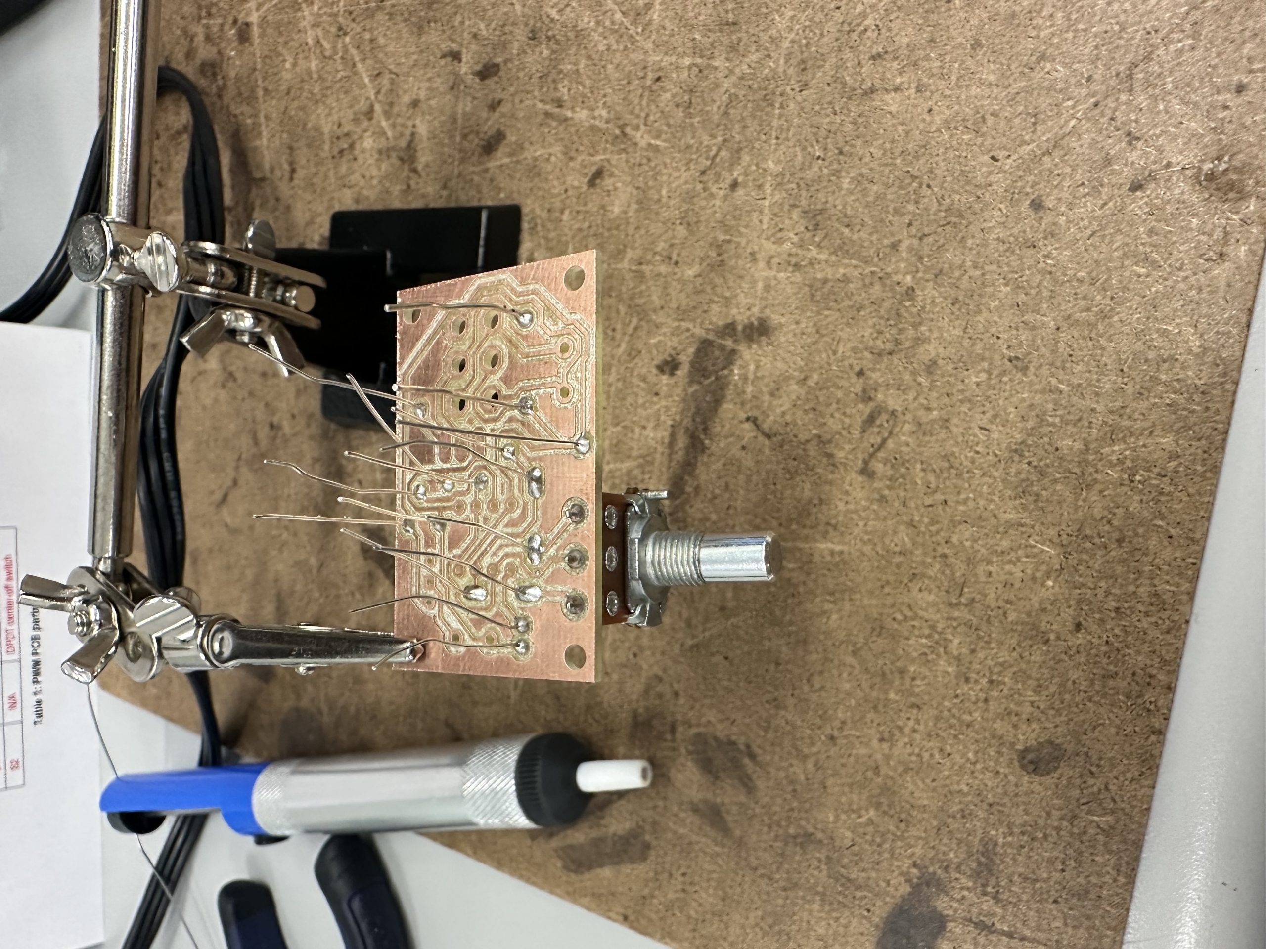
In this project I was tasked with desinging a circuit board for a Pulse Width Modulation system that could control the speed and direction of a DC Motor with a 555 timer. We were given wire schematic on paper, and I had the make the same schematic on the Autodesk Eagle Schematic software, once I completed this part of the project I had to made a printed circuit board (PCB) from scratch using Autodesk EAGLE as well. Once the PCB board was made I had to solder all the parts to it ensuring the finished board was ‘neat’. Once was the board was soldered I tested the board at 12 volts on the input, and using the board I controlled the speed and direction of the DC motor from no speed to full speed.
Project Constraints
- Must be below 2.2 inches in square area
- Must control the direction and speed of a DC motor
- Must be soldered without issue

Figure 1: PWM Schematic in Autodesk EAGLE

Figure 2: PWM PCB Board in Autodesk EAGLE

Figure 3: Soldering of the PWM Board

Recent Comments