Fire Robot Motor Mount
This is a short how-to for the motor mount I designed and built for my Fire Robot.
Click here to view the type of stepper motor we will be using with all the measurements.
Designing The Motor Mount
For this project, my software of choice was Creo Parametric.
First I drew the “L” shape and then extruded it evenly on both sides of the front datum.

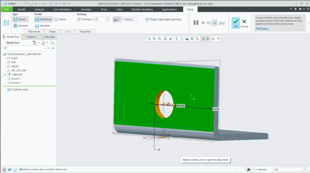
Next, I made a big hole for the motor to sit flush with the side of the mount. Using the dimensions from the link I was able to find the height from the base of the mount. Extruding the bracket on each side gives me the front datum to use as a reference perfectly in the middle of the bracket on the X-axis.

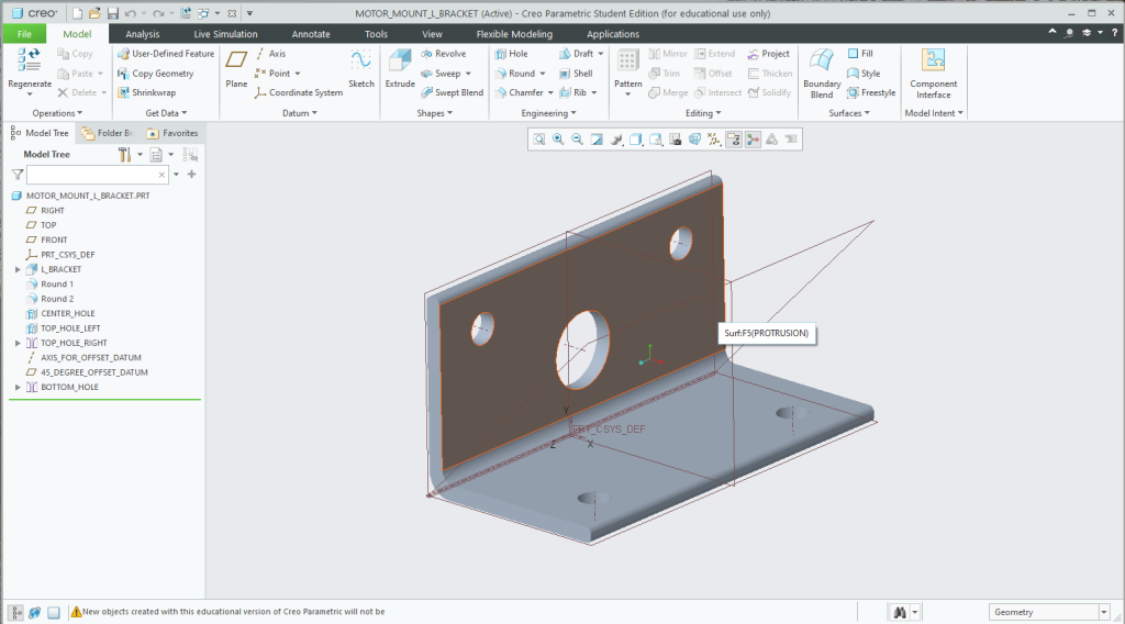
After the hole for the motor shaft, I needed to make two holes for the mounting points of the motor. I did this by using some construction lines to locate the middle of one circle. After I made that hole I could mirror it over the front datum to the other side.

After I got the two top holes in place I made an offset datum at 45 degrees and grouped the top holes and mirrored them to the bottom part of the “L” in the bracket.

Finished motor mount.

Then I went through and added some rounds and fillets then sliced it in PrusaSlicer to 3D print.
3D Printing The Motor Mount
I uploaded the 3mf file from Creo in Prusa and selected the printer and layer height I wanted for the print. For the particular size of the motor mount, the Prusa Mini would be the perfect size printer for the project.

After about an hour of printing, it was time to test and see how the motor fit in the new mount.


Recent Comments