Zipline Project Fall 2023, Western Carolina University, NC, Professor Hugh Jack. Team: Nicolas Gonzalez, DeAsia McQueen, Sydney Kilgus-Vesely.
Due: September 20, 2023
Problem Statement: This assignment’s problem statement is to design and build a device that can only travel in a forward direction along a paracord zipline using only materials provided by the professor and available within the MakerSpace lab at Western Carolina University. The paracord will be connected above the floor at both ends, with a certain amount of slack within the line toward the endpoint connection. This slack will test the ability of the assembly to halt upon backward motion.
Objective: This project aims to design a zipline device using Fusion360. Then, prototype and assemble the device using the materials located in the MakerSpace or approved by the professor. Due to the project’s aim to see how far the device travels forward from the starting position to the stopped position, the team will test the distance traveled by each prototype and design.
Scope of Work: Students were provided an objective with specific constraints. Materials purchased by the professor included small bearings, metal rods of a particular size range, metal BB gun pellets, and wooden dowels were available. The only other acceptable materials were the tools, adhesives, filament, and 3-D printers within the Makers Space Lab. Students were placed in teams and instructed to meet regularly, brainstorm, design, and create a zipline device to be tested within three weeks of the assignment announcement and description. No external propulsion or energy storage was allowed. The grade is based on the performance of the final project during class testing.
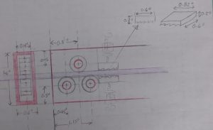
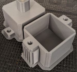
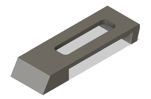
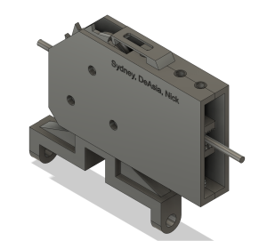
The initial design for this project consisted of a 3D-printed chassis that housed three axles and three bearing wheels (Figure 1). The initial design also involved a ballast that would attach to the chassis. Due to its complexity, the ballast box was printed (Figure 2) but never designed to connect to the chassis.
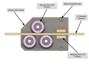

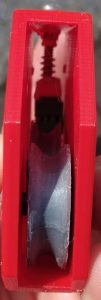
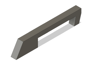
Because the provided bearings had a flat circumference rather than a chamfered one, a bearing cover CAD model was created and printed to fit over the bearing snugly and provide better guidance of the device along the rope (Figure 3); revision 1.0 of the zipline device is similar to that of a pulley block and wheel assembly, as seen through the assembly’s section view (Figure 4). The initial concept for the one-way motion constraint was to use angled fibers on a block that would slide along the paracord with little resistance in one direction but catch the paracord fibers once backward motion commenced.


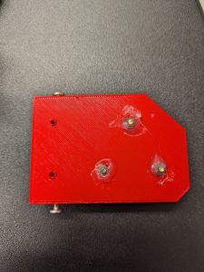
Further discussion and design for this resulted in 3D prints of two blocks with curved small extensions angled in one direction only, as shown in Figure 5. These two blocks were glued to springs and attached to the chassis using screws and threaded inserts that were melted into the plastic chassis (Figure 6). The adjustable screw and spring allowed for increased or decreased tension above and below the rope. Three ½” by 19/16” bearings were inserted into the three 3D printed bearing covers (Figure 7) and inserted into the assembly using 3/16” diameter brass rods (Figure 8).
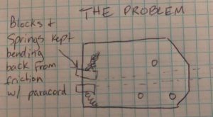
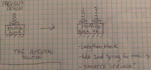
Upon initial testing on September 13th, 2023, a few problems arose with the Revision 1.0 prototype. Mainly, the two frictional stop blocks provided too much friction and needed more stability on their spring mounts (Figure 9) to make the device meet the project’s Performance Requirements. To combat this, new revisions were designed to improve the device. The printed stop blocks were increased in length, and an additional spring mount was added for each block to add stability (Figure 10).
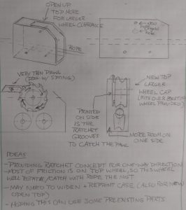
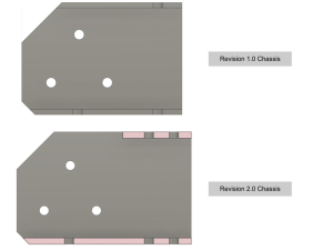
As a failsafe for the one-way movement constraint of this project, an additional mechanism was designed to prevent backward movement: a rachet and pawl (Figure 11). The ratchet was designed to sit on one side of the top wheel. The small pawl was designed to glue to the top of the chassis (Figure 12). The width of the chassis was increased to make room for the added width when installing the ratchet, and an opening was created at the top so the pawl sitting on the top could reach the ratchet (Figure 13). The pawl and ratchet were printed. This design was deemed Revision 2.0.


One team member created a second revision for the pawl to allow for adjusting the friction the pawl had on the ratchet (Figure 14). This design involved a rounded slot in the center of the pawl so a screw could fasten it at any given slot position. To account for securing the pawl to the top of the chassis, an additional hole and threaded insert were included in the assembly (Figure 15). This Revision 2.1 assembly was modeled in Fusion360 (Figure 16). The new pawl and chassis were printed.
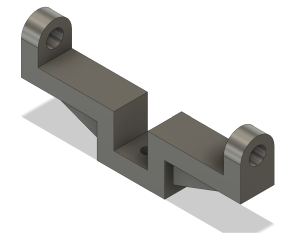
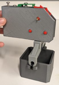
To add the necessary weight for gravity to overcome friction and for the assembly to travel along the paracord, the small ballast box printed for Revision 1.0 was attached to the chassis using a mounting bracket (Figure 17). The box was filled with metal BB pellets to add the needed weight. The box was attached to the mounting bracket with zip ties in the final assembly. This Revision 2.2 was modeled in Fusion360 (Figure 18) and assembled (Figure 19) for testing and submission.
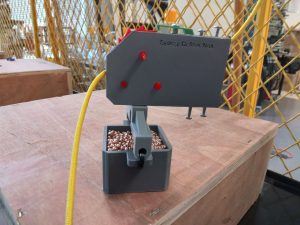
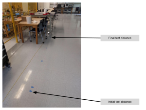
Final testing was conducted on September 20th, 2023, using the same test used for Revision 1.0. The zipline was run through our device and hung from the top of a door. Our first test showed that the revised stop blocks still added too much friction, so we removed them from our assembly. We then tested our device with different amounts of metal BBs in the ballast box (Figure 20). The initial test with no weight moved the least horizontal distance, at around four feet, but as we increased the weight, the device traveled over fifteen feet (Figure 21). We are confident that filling the ballast with the maximum amount of BBs will allow our device to travel the furthest. Final testing and grades based on the performance of each team’s device will be on Monday, September 25, 2023. Documentation for this assignment is currently due September 20, 2023. Therefore, no final results may be provided before the due date.
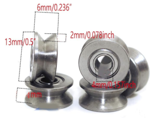
These parts can be found at the Amazon link here. The chamfered circumference of these bearings was referenced heavily when designing the bearing covers in Figure 3
Sydney was responsible for most of the design and CAD detailing of the device. I was involved in the device’s design, fabrication, and assembly. The prototype fabrication primarily used 3D printing, which Nicolas and I were both largely involved in. Nicolas assisted me with most of the 3D modeling and assembly process. Sydney’s background in drafting and graphics and her current position as a Mechanical Engineering student put her in a desirable position to handle the design and details of our project. I used the MakerSpace for past projects and was, therefore, more familiar with the materials and tools in the space. I also showed proficiency with 3D printing. Nicolas has a strong background in 3D modeling, including with Fusion360, which proved vital to 3D printing the needed parts. Throughout the project, the work was spread thin across the team members at specific points. It was hard to do many stages of this project simultaneously, but each team member pulled their weight throughout the project. For example, Nicolas was not as adept in mechanical design but largely participated in the 3D modeling for the two prototypes.
We used a ratchet to stop the device from going back and make it easy to thread the rope through. However, there were other ideas we could’ve used, like a pendulum or flaps that would have a similar function to the stop blocks. These ideas were scrapped for the stop blocks and later the ratchet for not having enough time to calculate the physics to make them work.
The original design was a hollow box-like shape inside the rope. The bearing covers came later, as did the rod couplings. With the stop blocks, we made several versions from one with 2 and 3 spaces to find one with good friction. The only problem is they needed less friction and did their job too well. Screws with springs were used to move the stop blocks up and down to give space for the rope. It used to be one spring and screw for each block, but we made the blocks longer, so we needed two springs and screws for each one, but the friction was still too much. So we took them out and had only the ratchet to catch the rope, and luckily, during the test run, it worked with enough weight. We didn’t deviate from the original concept much, as we only added minor features until we optimized our success.
Inventory:
- ½” x 9/16” Bearings with a 3/16” inner diameter (3)
- 3/16” brass rods (1)
- 6/32 threaded inserts and screws (6 of each)
- 3D-printed chassis with axle holes (1)
- 3D- printed bearing coverings (3)
- 3D-printed stop blocks (2)
- 3D-printed ratchet and prawl (1)
- 3D-printed brass rod couplings (3)
- 3D-printed ballast box (1)
- 3D-printed mounting bracket (1)
- Zip ties (2)
- Metal BBs (1500)
Recent Comments