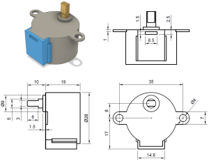
 For today’s post, I will be discussing the process for designing and 3D printing a motor mount for my Fire-Fighting Robot project. To begin this process, I found an online image with the dimensioned drawings for the motor I will be using, they are located here(https://cookierobotics.com/042/). The exact image I used is located on the right. To get started, you’ll need to open up your CAD software, I used Onshape, and begin a sketch. Then you will insert the image into the sketch.
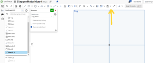
 To insert the image, click the drop-down arrow shown in the image on the left, and click insert image. On the bottom of the dialog box that appears, there is a button labeled import. Click the button and proceed to import your image. Once your image appears within the dialog box, double-click it to add it to the sketch, and then draw a rectangle wherever you would like to place the image.
 Now that the image is imported, we have to do the hard part, scaling the image. in order to do this, pick out an easily defined dimension on the drawing (it can be either vertical or horizontal), and draw a line to match it. Make sure the line you draw is perfectly horizontal (or vertical, depending on which line you choose to scale based on), and then set its length to be exactly the same as the length of the dimension you are using to reference. Now, you have to increase or decrease the size of the image until the dimension in the sketch and the line you drew are approximately the same length. It helps to move the image around so that the dimension you chose and the line you drew stay as close together as possible. It’s important to note that you don’t have to get them to be exactly the same, but the more accurate you can be, the better. Off to the right is how it looked when I completed this process. The blue line is the one I drew in CAD, and it’s almost exactly the same length as the length between the dimension lines.
 Once you’ve scaled the image, you can close the sketch, and then begin a new sketch. In your new sketch, draw out all of the necessary pieces to mount your motor. For me, this was the two mounting holes and the hole for the output shaft. Try to align the features to their corresponding parts on the imported drawing, but make sure that you use construction lines to keep everything at the proper distance from each other. Now you can design the actual plate of the mount around all of the holes. I just used a simple rectangle. Once you’ve done that, you can save the sketch and extrude it, and it should look something like the image on the left. You can alter the length of the extrusion based on your strength requirements, but mine was just 3 mm.
 Once that’s done, you will need to add the top part of the motor mount, which will mount to the chassis of the vehicle. To do this, simply add a rectangle to the top of your previously designed piece. This rectangle should be as tall as the length of your previous extrusion. Be sure to use the image of the motor to make sure this new rectangle will not make contact with the motor, and then extrude this rectangle long enough that you can place mounting holes on it. If you have mounting holes on the chassis already, you should match the holes on your motor mount to them like we did to mount the motor, or you can simply place two holes (you can add more if you need extra strength) and then design the holes on the chassis to match the holes you placed on the motor mount. Lastly, you can round off those ninety-degree angles between the two extrusions, and then you should have a finished part that looks like mine on the right.

 Now that you’ve designed the part, the next step is to prepare the part to be printed. To do this, export it from you’re CAD software and import it into your 3D printing software (I’m using PrusaSlicer because I will be printing on a Prusa Mini). I chose 0.15mm QUALITY for print settings, PLA for my filament, and I used 20% infill. Off to the left, you’ll see what my part looked like after 3D printing, with the motor mounted to it.

Recent Comments