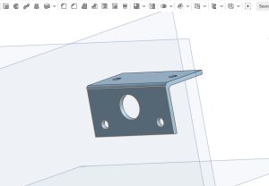
Importing an image to onShape while you are designing a part has many benefits. Specifications are easy to reference and you can align your sketch with the images’ lines. In addition, overlaying the product specifications with your sketch makes it easier to position screw holes. I will be designing a “L” shaped stepper motor mount. But before we get started…
Tips for onShape (and other CAD programs)
- Rename sketches, extrusions, and parts to make specific features easier to edit in the future
- Familiarize yourself with the keyboard shortcuts
- Use a mouse
- Draw circles and other shapes outside of your main sketch to prevent accidental constraints from forming
Step 1. Find a specifications sheet for the product
I am using a specification page by Cookie Robotics for a 28BYJ-48 Stepper Motor. Link: https://cookierobotics.com/042/. When you find a specifications page, save it to your computer as a PNG or JPEG.
Tip: Since unconstrained lines in onShape are blue, try to avoid using a specifications page with blue lines.
Step 2. Adding an image in onShape
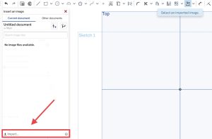
The button to upload pictures should be on the right side of the toolbar. It can have 2 different appearances.
.

When you add the image to onShape don’t worry about its initial size. Step 3 is all about scaling the image to the correct size.

Tip: If you can’t find a tool in the toolbar make sure you aren’t zoomed in too much and you are in the Sketch mode.
Step 3. Scaling your image
Now that you have added your image, we need to scale it to the correct size. In the same sketch as your image, draw a line and dimension it to the same length as a line in the image

Second, increase and decrease the size of the image until the line on the image is close to the same length as the line you drew. You should move your line as you change the size of the image in order to get the most accurate comparison.

Step 4. Design your product
In a new sketch, you can start designing the part that you need. In my sketch, the circle in the middle is a hole for the shaft of the motor. The two smaller circles are screw holes that will be used to attach the motor to the mount. The small rectangle at the top is where I will create an extrusion with 2 screw holes.

Next, you need to extrude add or extrude remove the parts of your product that you want to be solid or holes. The top part of the mount was created in a different another sketch and extruded separately.
.
Tip: Make the diameter of the holes slightly larger then the shaft, because the overall dimensions of the finished product will be slightly smaller then what is in CAD.
Step 5. Printing your product
To export your product, right-click on the part name in the side menu and click export.

My Print Specifications
- Printer: Prusa MINI
- Materiel: PLA
- Slicer: 20% Infill

Finished Product


Recent Comments