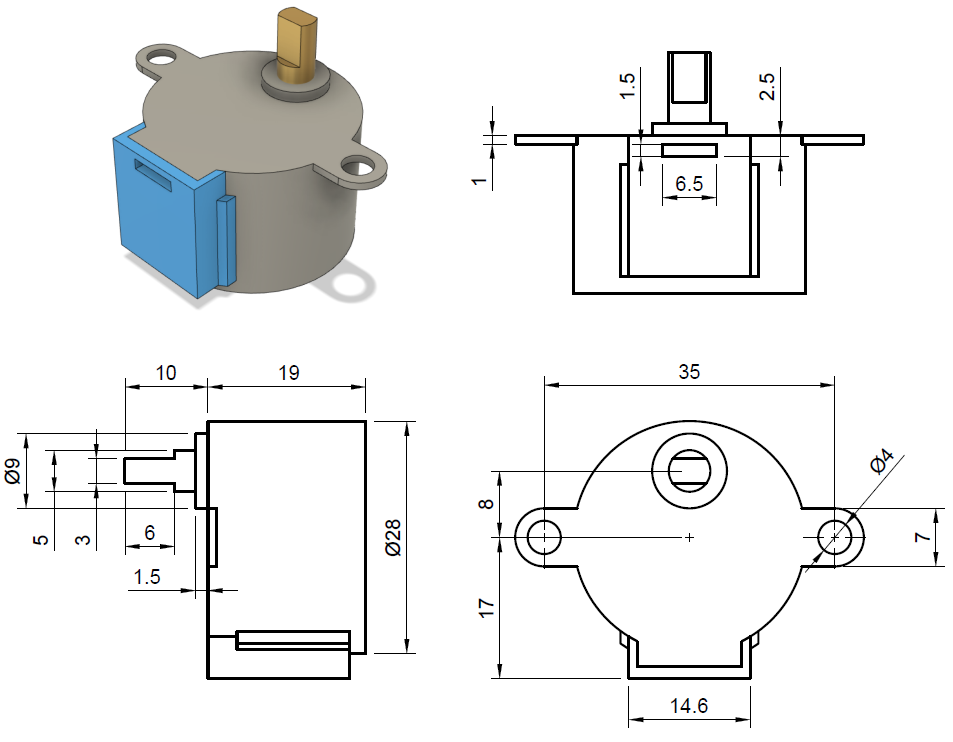
As part of the final project for my first-year engineering class, I had to design one of the wheels for the fire-fighting robot. The wheel had to fit on a 28BYJ-48 stepper motor and have a hole on the side for a 3 mm screw. I used this image from Cookie robotics for the dimensions of the stepper motor. However, due to the way 3D-printing works and other variables, just copying the dimensions for the wheel’s hub will not let it fit over the stepper motor. Since the size I tell it to print is not what comes out. As a result, I had to print multiple variations and edit each one slightly until I printed a hub that would fit. Since I had to print multiple versions, I only printed the hub of the wheel instead of the entire thing to speed up the print and save material. I changed the inner width of the hub for each iteration until it would fit comfortably on the motor. Furthermore, I changed the total diameter on the final version so the screw would have more material to grip onto. I used this formula for determining the size I should print the next hub:
How big to create a part in CAD = (What you originally told it to print) / (size it actually printed) * (Size it should have printed)
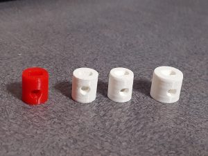
It took four different iterations until I found the correct dimensions. My final dimensions are a total diameter of 11 mm, an inner height of 5 mm, and an inner width of 3.3 mm. Here are all of my different attempts, with the final hub design being on the far right.
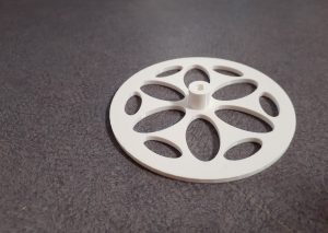
After finding the correct dimensions for the hub, I could move on to designing and printing the entire wheel. I designed the with a pattern of oval holes to remove excess material and speed up print time. Here is the final product.