


The task we that had to solve was to put out a flame at the end of a short maze using a robot. My partner, Nick Pagan, and I decided to create a robot using our knowledge from our ENGR-199 class.
Our approach was to construct the robot from the given stepper motors, Arduino circuit board, driver boards, relay switch, thermistor sensor, fan, bread board, and ultrasonic sensor. To piece it all together we had to 3D a few components as well as construct the chassis from posterboard.
The goal with this assembled robot was to use the ultrasonic sensors to detect the walls of the maze, the stepper motor to turn the wheels, and the thermistor sensor to determine when to stop and extinguish the flame with the fan controlled by the relay switch.
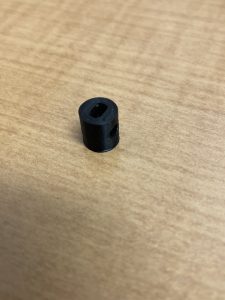
The parts we had to print/design ourselves were the motor mount using a sketch of the dimensions of the stepper motor, the wheels which had to be of equal diameter, the hubs that had to fit the motor shaft, and the ping-pong ball holder to stabilize the body of the robot.
A few problems emerged as we worked, and we had to come up with solutions to these unique issues…
- The first problem came to me when I printed the motor mount and used the wrong filament which caused warping and gaps. I then reprinted with PLA Polymaker and got much better results.

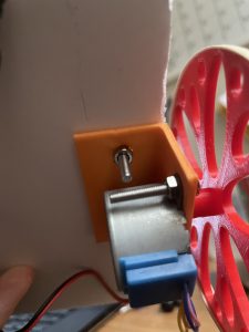
2. The next issue was with the wheel hub. After printing on the round side and getting a warped, messy piece, I rotated it in the CAD software to the flat side, but the hole using the given dimensions was still too small for the shaft. I measured the hole and adjusted the dimensions on OnShape to accommodate this difference from the software to the physical print on the LulzBot, getting the correct size and full wheel this time.


3. While assembling our robot, we made the mistake of using the bread board the wrong direction with the flame sensor. I turned the board horizontally, but this made the body unbalanced. I then reconstructed it again with a new chassis that, along with the ping-pong ball-holder I 3D-printed, was stable to drive and not tip forwards.


For the programming of the robot, we used an Arduino circuit board and coding. Although my partner was the coder here, I still learned quite a bit. For example, we had to use a library for the stepper motor from the Arduino IDE. In order to use the library, it had to be downloaded then the header file was put as the first line of the code to make it work. To control the stepper motors, we had to split the commands to the right and left, sending one step at a time, then this block of code was used to make it travel forwards as one unit or turn (motors go opposite directions).


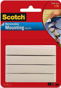
A few modifications that were made using outside knowledge/resources included how the parts were attached. Although the mounts and circuit board were screwed in with the given supplies, I used my own mounting putty to attach the other parts such as the battery pack, bread board, and fan. For the ping-pong ball holder, I actually used a Velcro strip with tape adhesive because the screw holes did not print. Additionally, I soldered the 9V batter power supply to a AA battery holder. Our wheels were also a custom pattern made on the CAD software.


In conclusion, I was very pleased with the end result and was glad to complete the task. If given more time, I would make the wheels straighter, the wires covered, and perhaps an additional wheel in the back rather than the ping-pong ball for a smoother drive. Overall, the code did great by completing the goal successfully. Although it would be much more challenging, it would also be practical to make it so the robot can turn both ways rather than only making right turns as in the given maze.