In this post, I will show you how to digitally draft and 3D-print a mount for the 28BYJ48 stepper motor.
Required Hardware:
- A computer to use Onshape.com
- A 3D-Printer
- A data transferring tool compatible with your 3D-printer
Required Software:
- A browser that is compatible with Onshape.com
- A cutting software that is compatible with your 3D-Printer, I will be using Prusa Slicer
Step 1: Open Onshape.com and sign in or make an account.
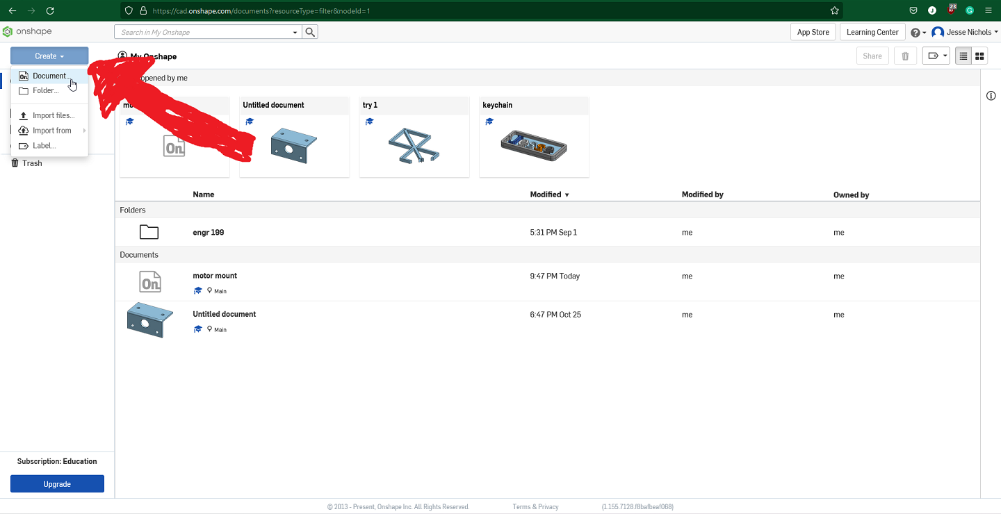
Step 2: Start a new document by clicking the “Create” dropdown box in the top left and then clicking document.
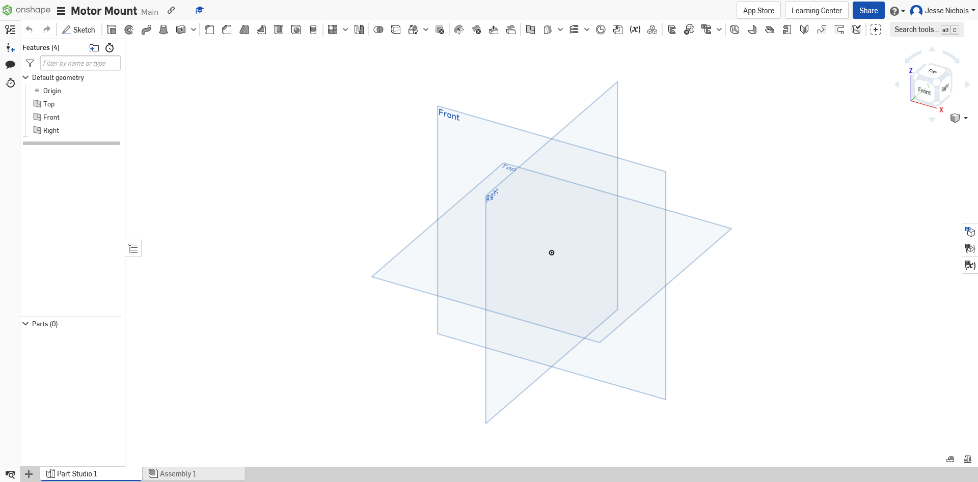
Step 3: From there you should name your document and your screen should look something like this:
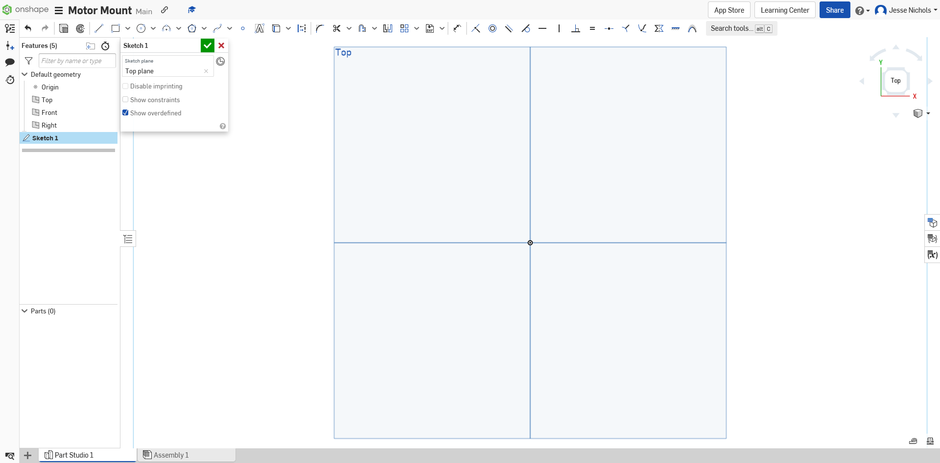
Step 4: From here you need to create a sketch, you do this by clicking “sketch” in the top left and then selecting a face. After doing that, your screen should look like this.
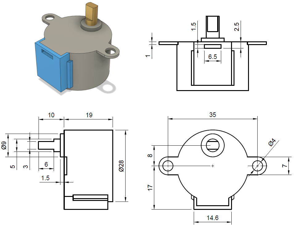
Step 5: Find a reference image for the motor, with dimensions. I will be using one from cookierobotics.com. This image includes dimensions in mm, so make sure that your Onshape document is set to that as well.
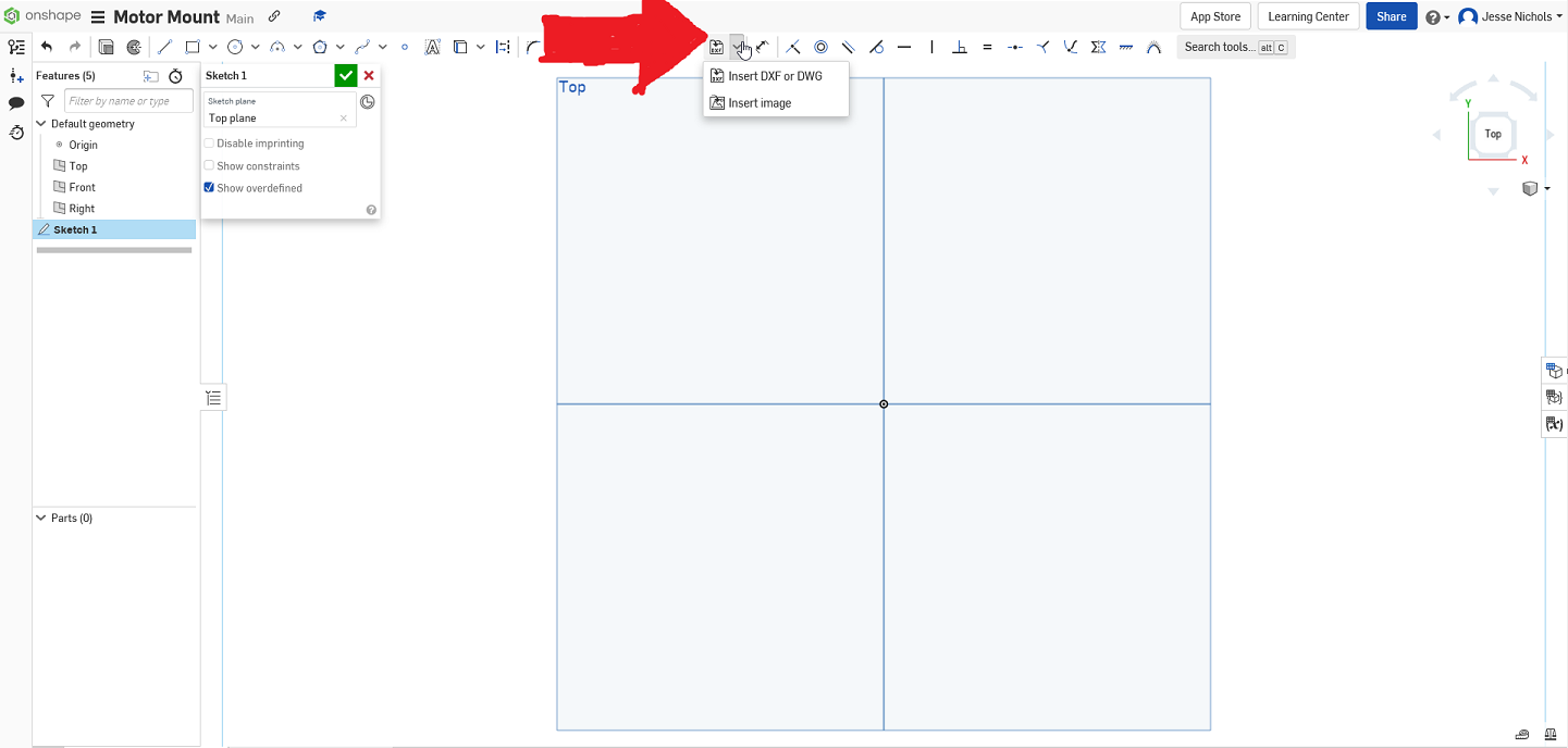
Step 6: Insert your reference image into your onshape drawing. To do this, first, select the drop-down box next to the “insert DXF or DWG” and then the “insert image” button.
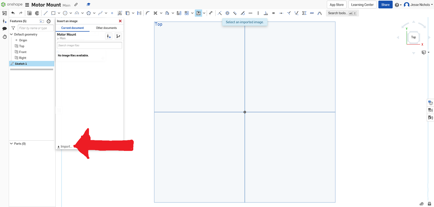
From here you should click the “Import…” button and then browse to your reference image on your computer.
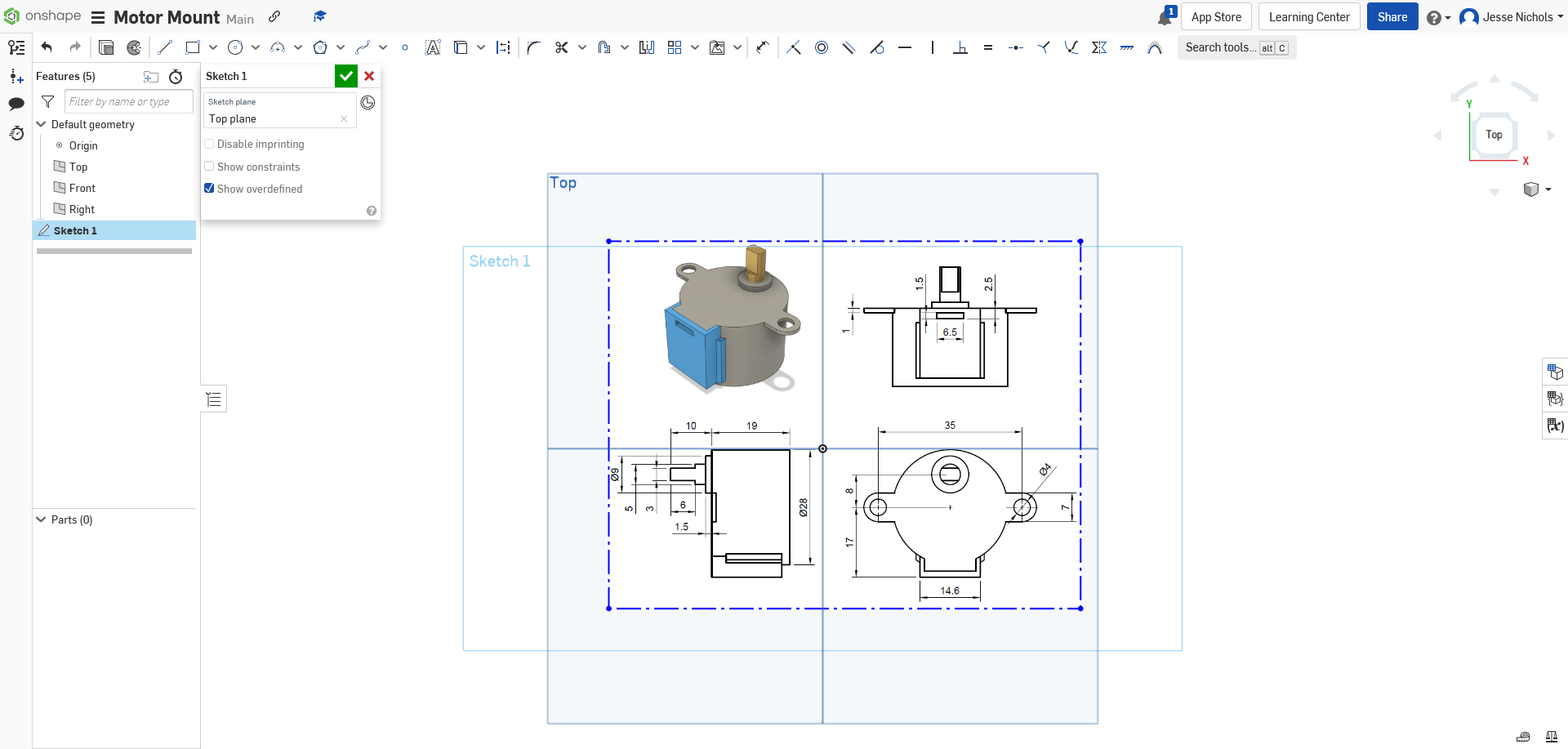
Step 7: After the last step, you click the image you uploaded and scale it to any size, we will scale it to the size we need in the next step.
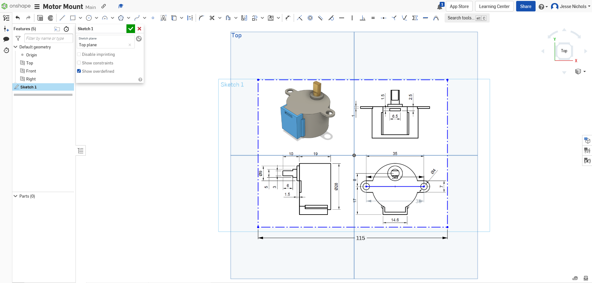
Step 8: Now we will scale the image to be 1:1 with the scale in the reference. First, pick a line on the part, I will use the horizontal 35mm line on the front face of the part. From here create a line anywhere on the canvas and dimension it to the same as what is written on the reference. Now dimension the image from earlier, you want to dimension the side that is parallel with the dimension line you picked. For the 35mm line, the side of the image we will dimension will be the bottom one. Now line up the line you made with where it is on the image and scale the image until they are as similar as you can get them. For me that was 115mm on the dot. In the end you should end up with this:
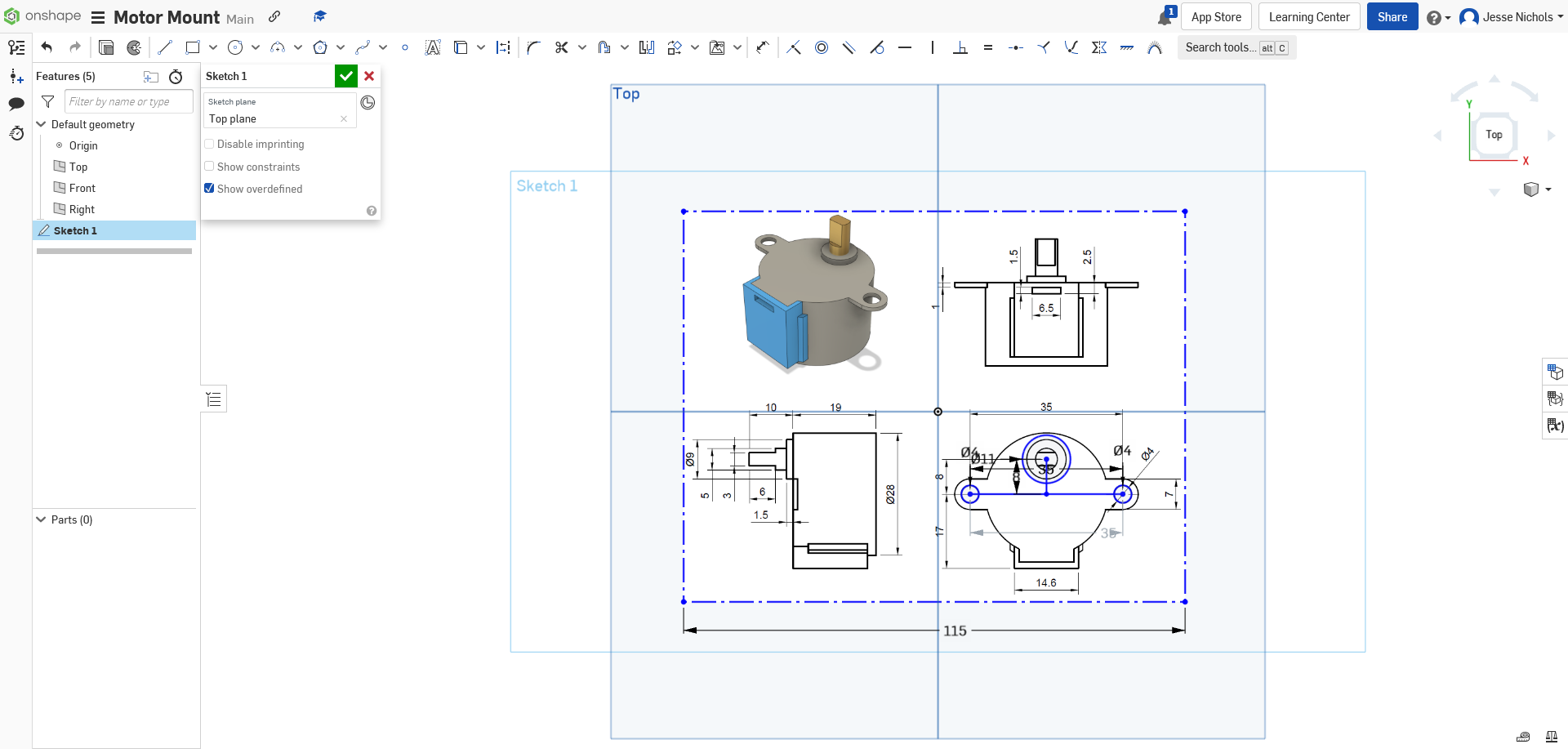
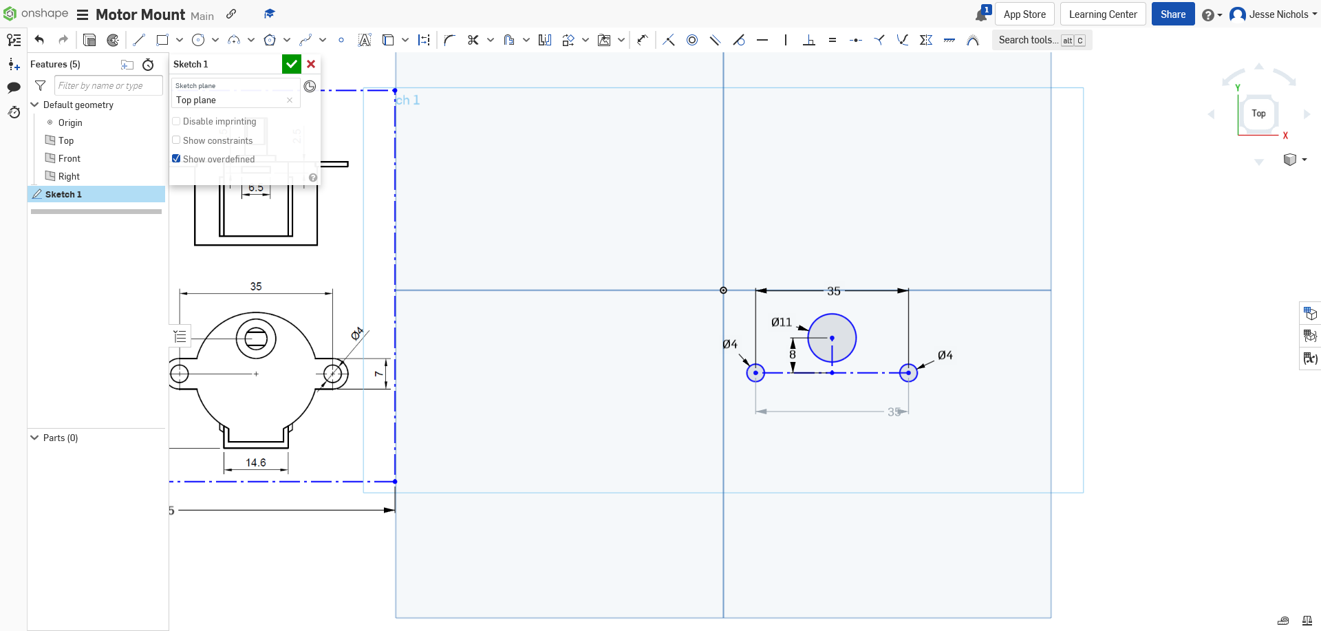
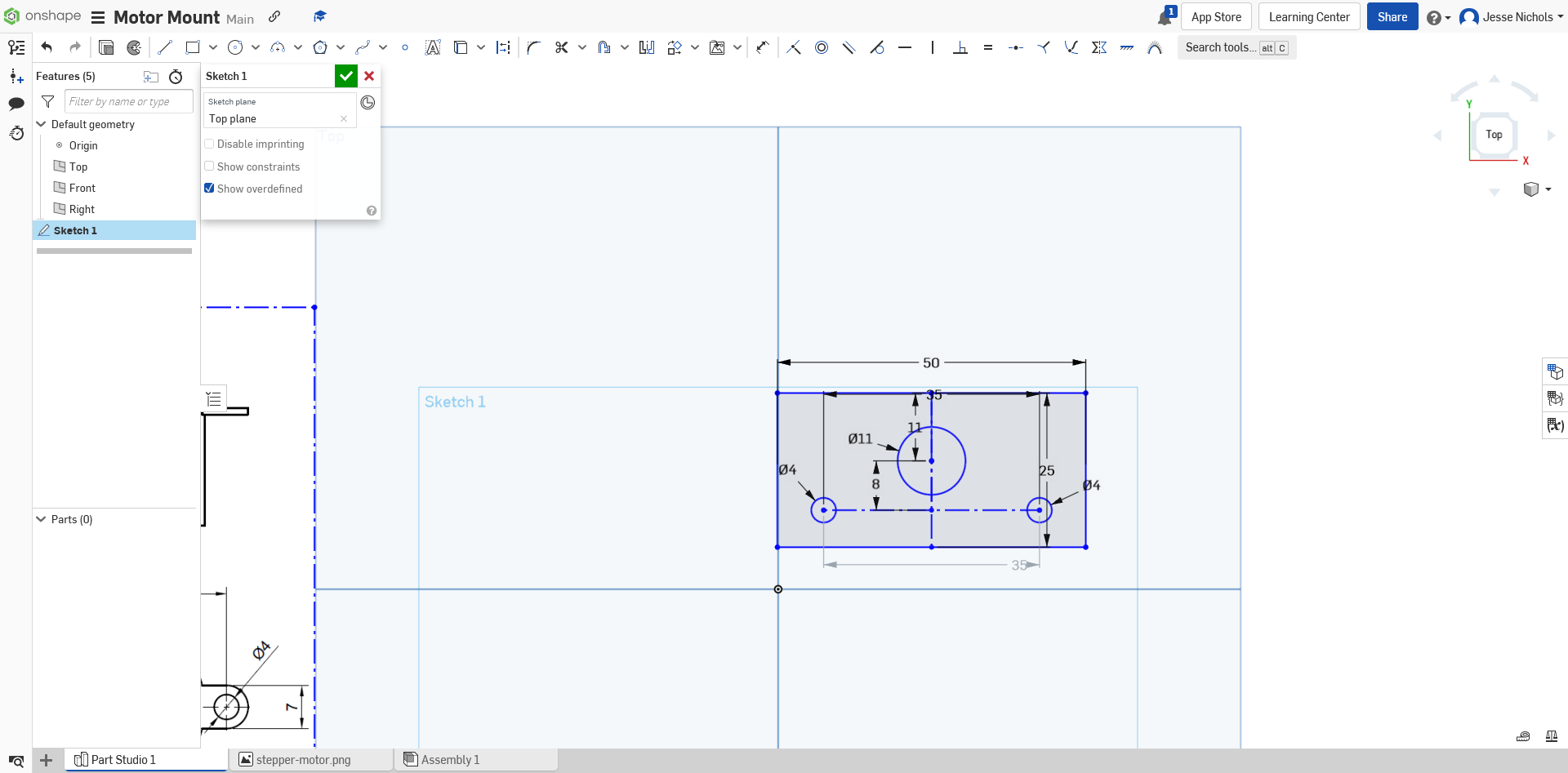
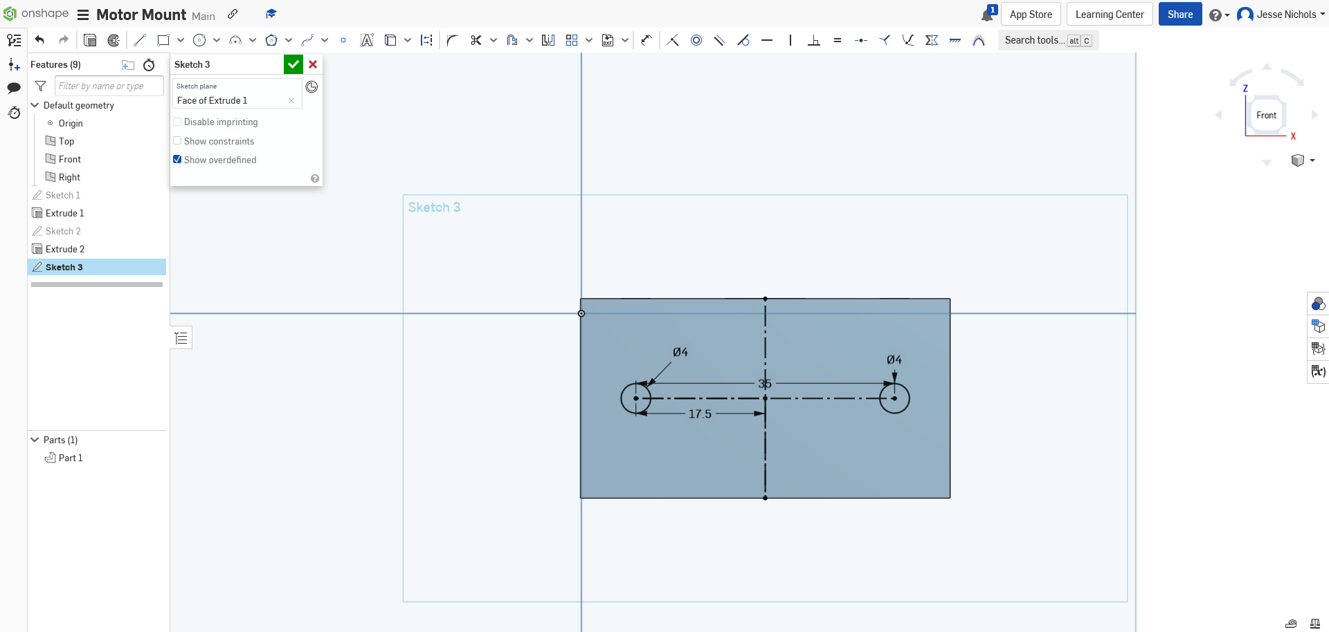
Step 9: From here make 2 circles, one at each end of the line, and make them each 4mm in diameter. Then make an 8mm line straight up from the center of the 35mm line and create an 11mm circle there. The 2 small holes will be for mounting the motor to the mount. The larger whole will be for letting the shaft of the motor, it is given a little extra space to account for inaccuracies in the measurements of the parts.
From here, we no longer need the image, so you can move it out of the way. Now you should make all of the lines that are not parts of the circles into construction lines.
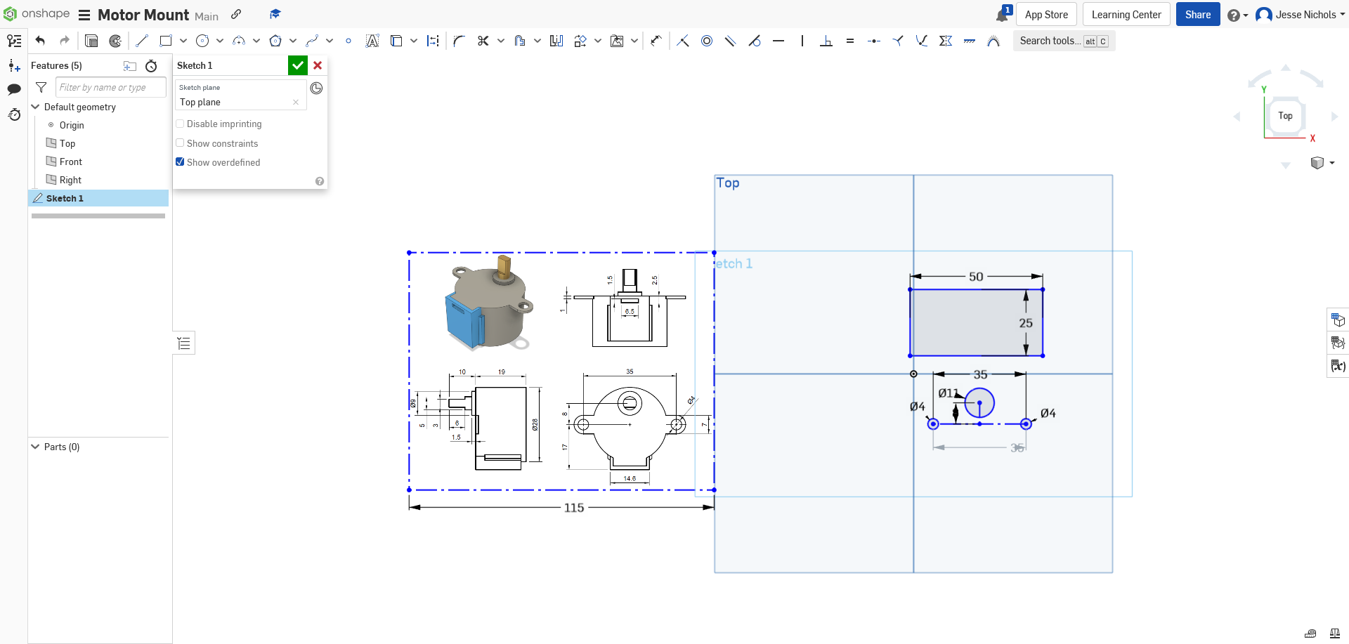
Step 10: Now we need to make the rectangle that the circles will be excluded from. You need to make a rectangle anywhere on the canvas with the dimensions of 25mm tall x 50mm wide. It should look like this:
Now create an 11mm construction line straight up from the top of the large circle and then set the middle of the top line of the rectangle coincident with the end of that line, You can find the center of the rectangle by making a construction line down the middle of it. You should end up with something like this:
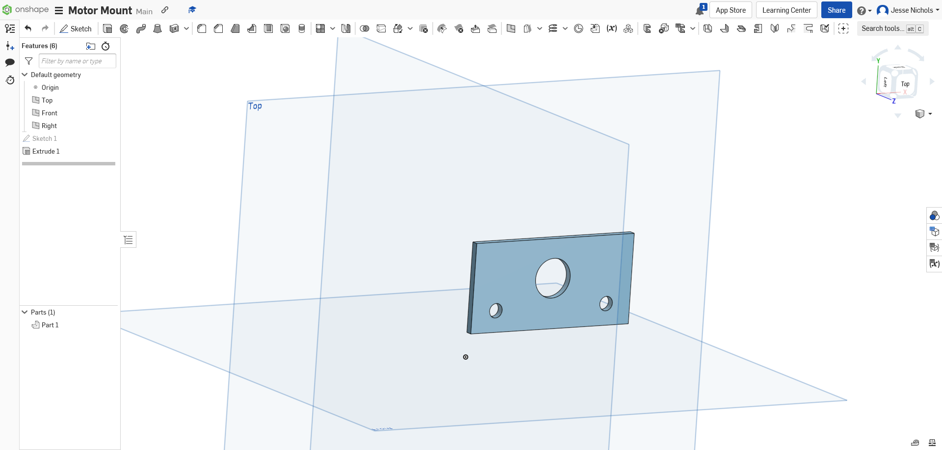
Step 11: Now click the checkmark and finish the sketch. Then extrude the part, excluding the circles, 2mm. You should end up with something like this:
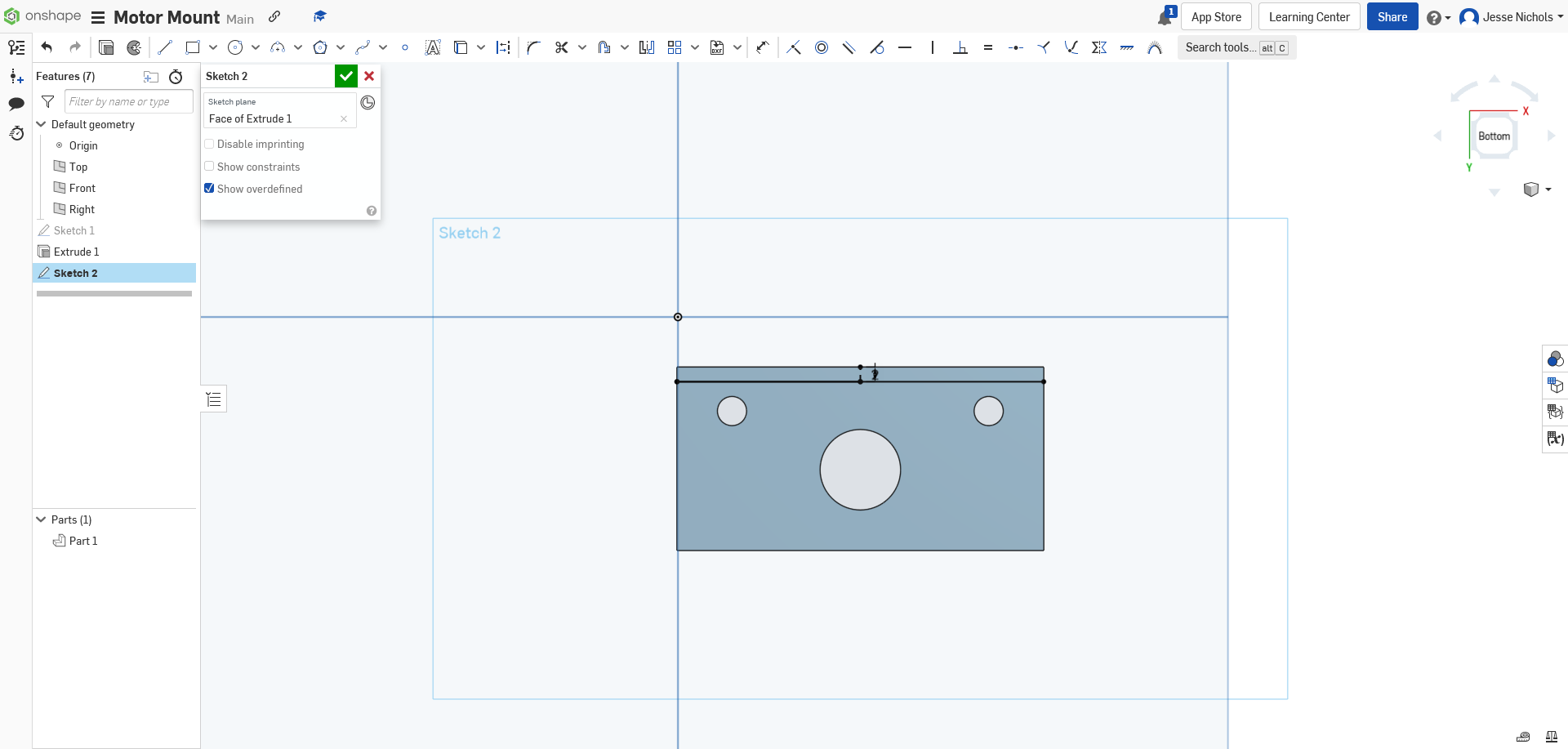
Step 12: Now create a new sketch on the back of the first part and create a line left-to-right 2mm from the side closest to the large circle. It should look something like this:
Step 13: Now you can finalize the sketch and then extrude the sketch 25mm away from the rest of the part. It should look like this:
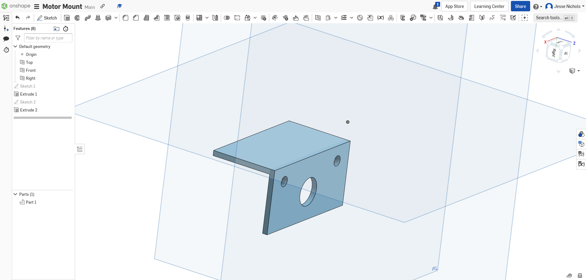
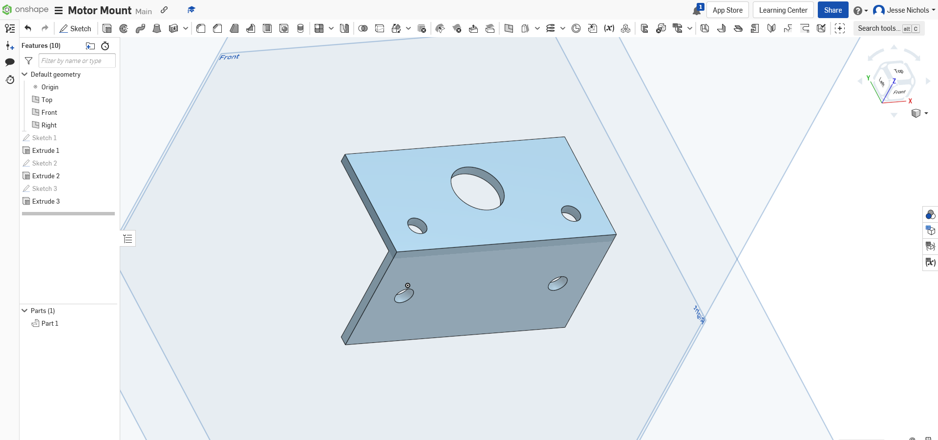
Step 14: Now we need the holes to mount the mount to the surface. I am going to put these the same spacing apart as the other mounting holes but in the middle of the new face. So you should create a sketch on the top of the new face and make the holes as I said. You should end up with this:
From here extrude them and you should end up with this:
Step 15: Now you should add a fillet to the inner and outer edges of the part, I chose a 2mm fillet. It should look like this:
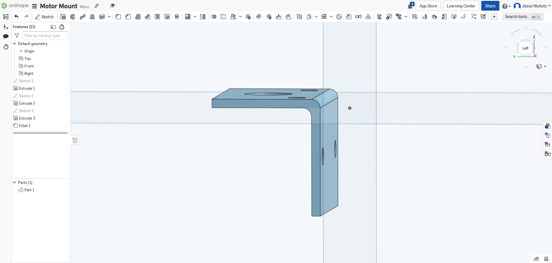
Now we are done with the 3D-Model.
Now we start getting the model ready to print.
Step 1: First you need to export your part from onshape, you do this by right-clicking on the “Part 1” button and then clicking export.
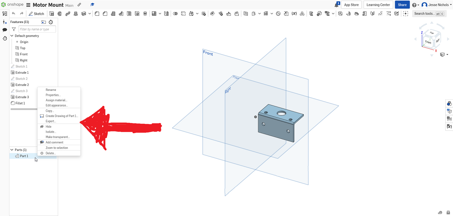
From here make sure it has the file type as 3MF and that it is set to download. Now hit OK.
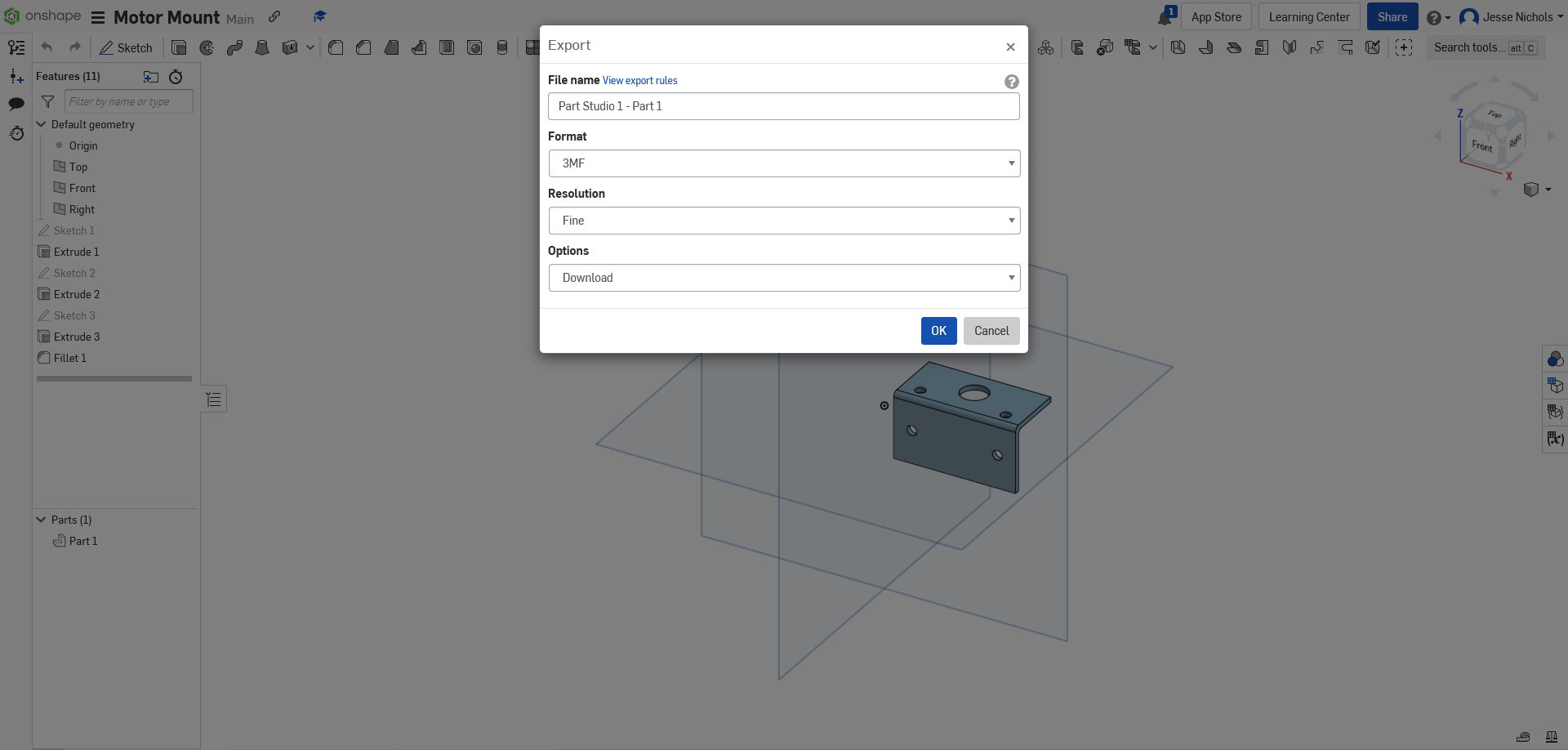
Once it finishes downloading you can move on to the next step.
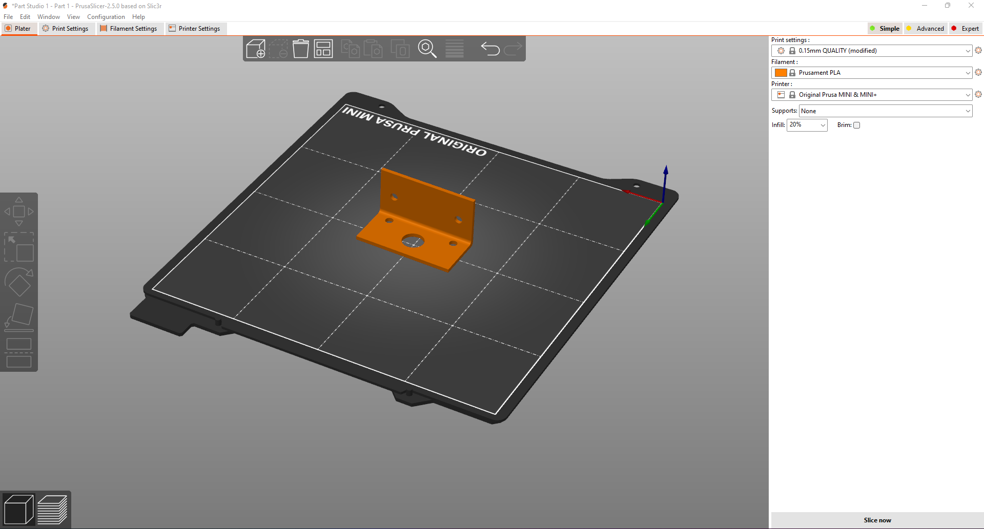
Step 2: Now you need to open Prusa Slicer to slice the model to be printed. Now open the model we saved earlier. My print settings are set to, Print settings: .15mm QUALITY, Filament: Prusament PLA, Printer: Original Prusa MINI & MINI+. Now choose your infill, I set mine to 20%, and verify that the part is sitting on the side that will lead to the least support structures. You should be fine to slice your part now.
Once you click slice now it should look like this:
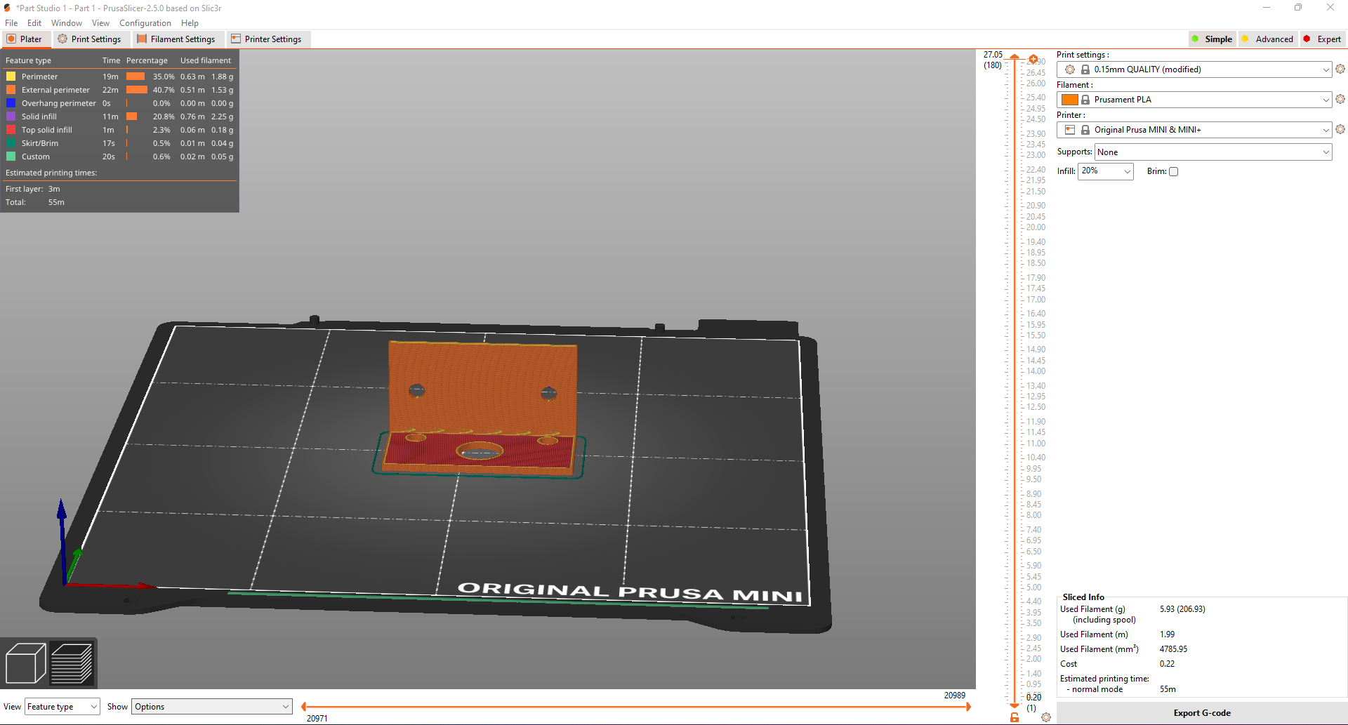
Step 3: Now you can export the G-code to your data transfer device, for me it was a usb thumb drive, and go print your piece.
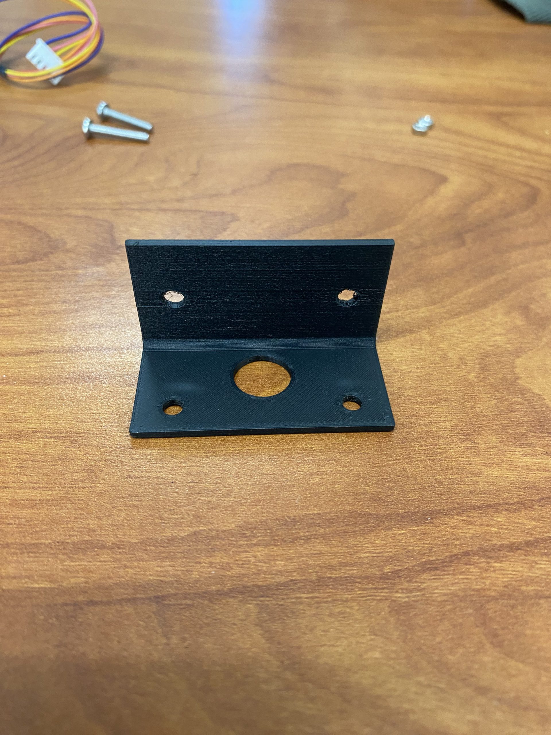
Step 5: Make sure to clear out any supporting structures from the print and you should be able to mount the motor to the bracket. It should look like this.
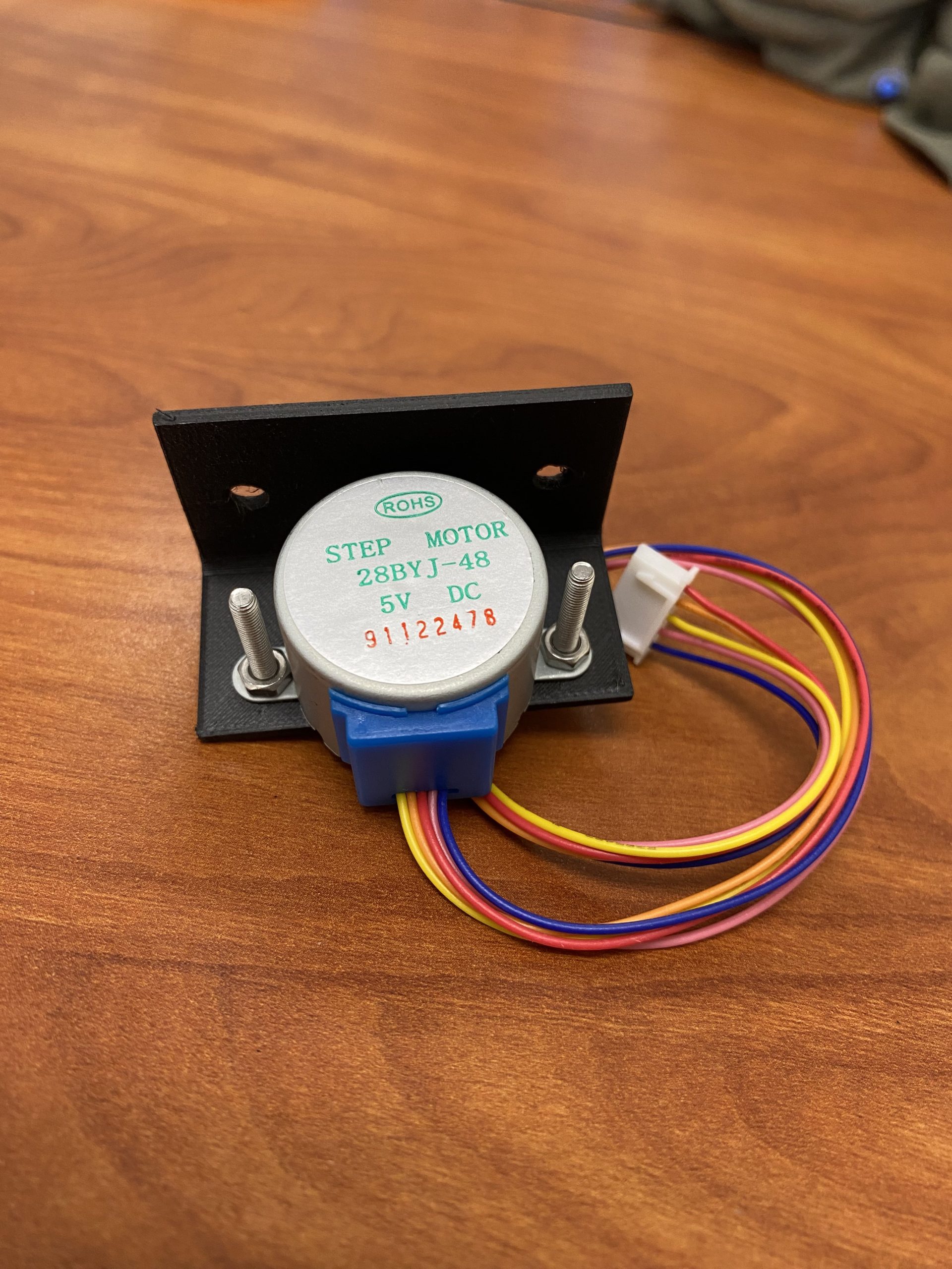
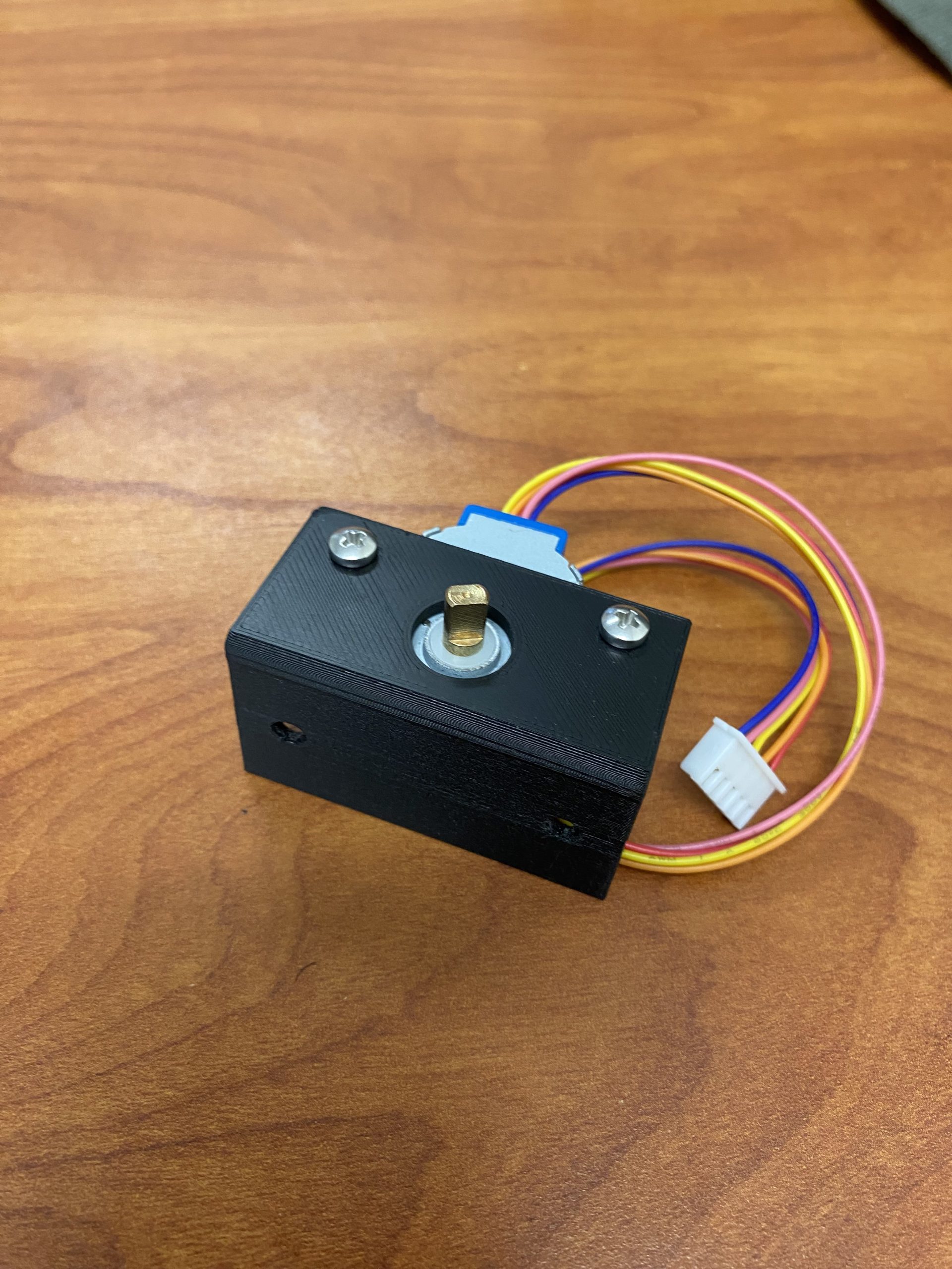
Now you are ready to mount your stepper motor to whatever you want.
Recent Comments