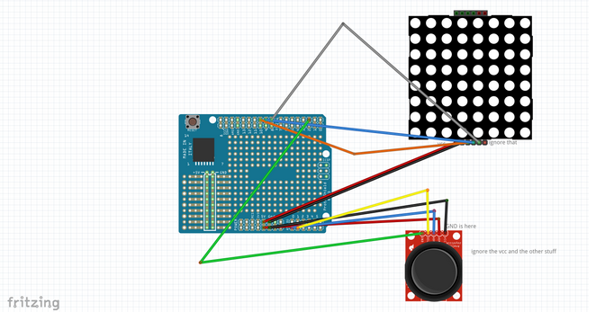
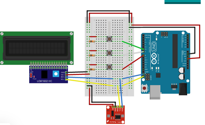
This project was purely elective. For an honors project in ENGR-199, Dr. Harris told me to go to Instructables.com, create.arduino.cc, and hackaday.com to choose three potential projects. The ones I chose were, a piano that used capacitive touch sensors instead of buttons (link), a version of “snake” that used the 8×8 display and the analog joystick (link), and an adjustable digital clock that could use the microcontrollers that we assembled early in the semester (link). Dr. Harris then reminded me that I have to add something to the projects, changing the code or hardware in some way and 3D printing something. The Changes that I came up with for the code and hardware for each of the projects are as follows, some way to change the key that the notes are played in for the piano, for the snake game I was thinking of adding sound to the game, and for the clock I was thinking of adding a chime for the hour. The 3D-printed things would be, a piano model for the piano, a sort of handheld case for the snake game, and a case for the clock. I settled on the piano and began working on it.
Images of the different projects from their posts on arduino.cc
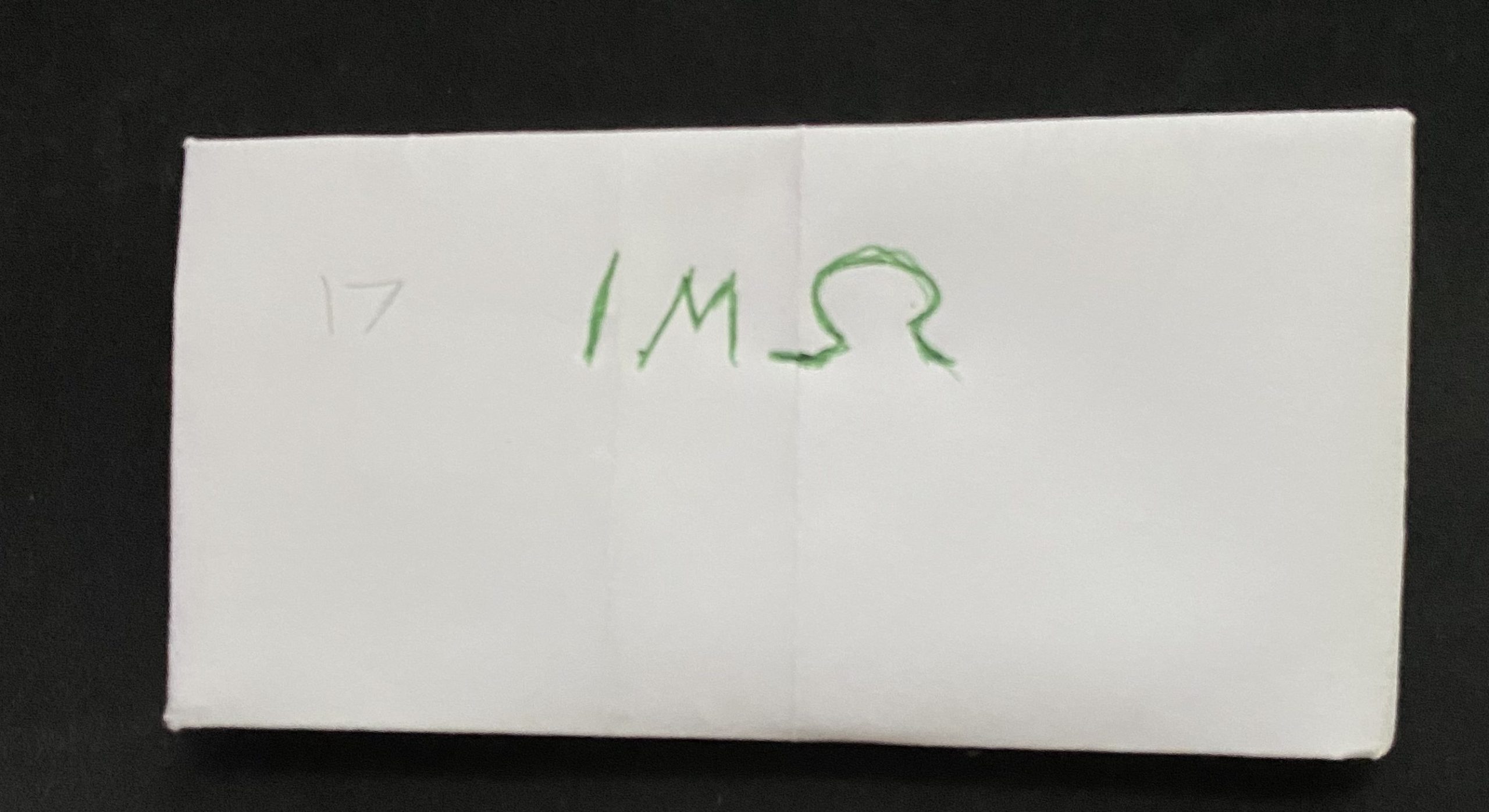
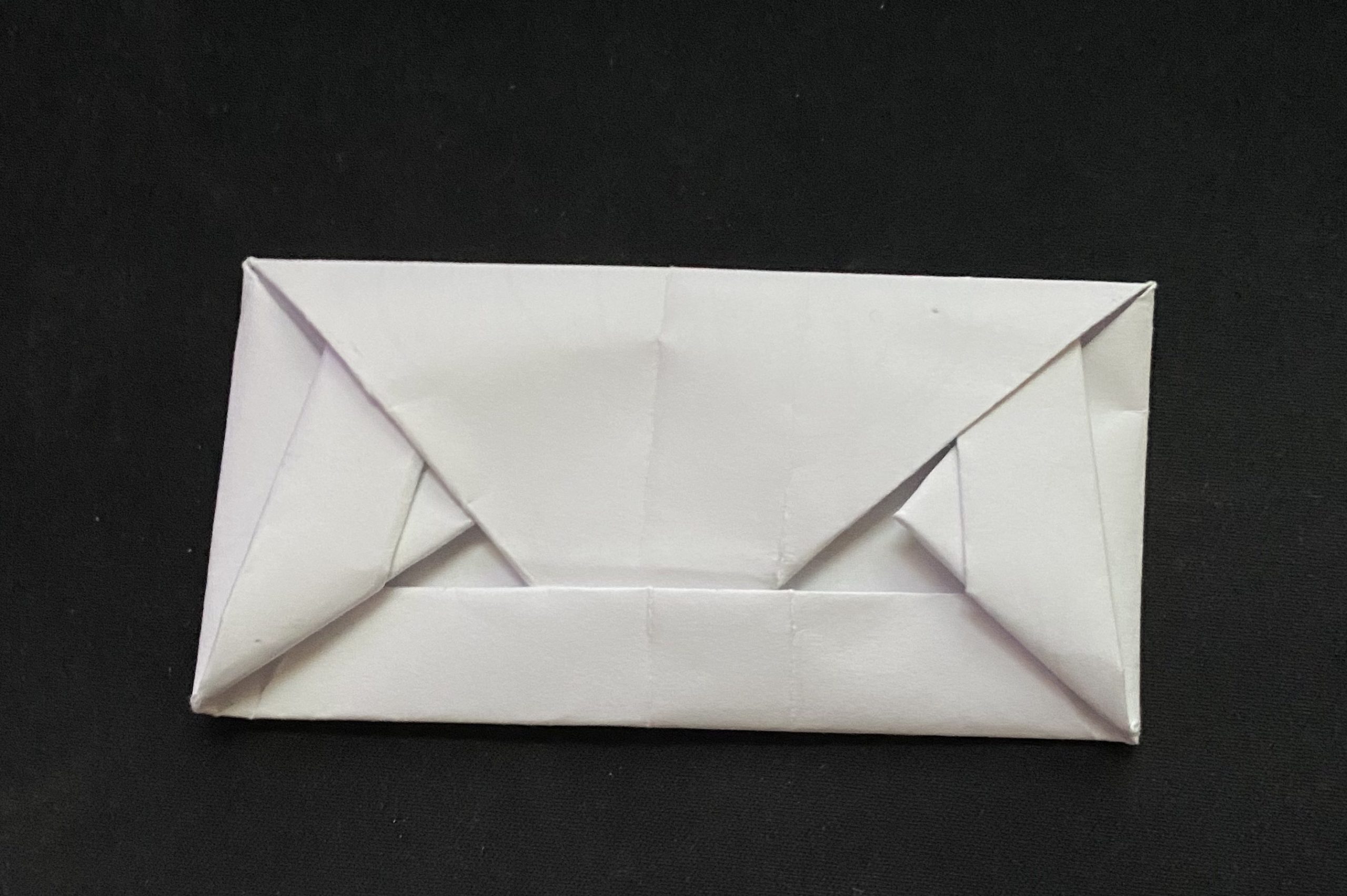
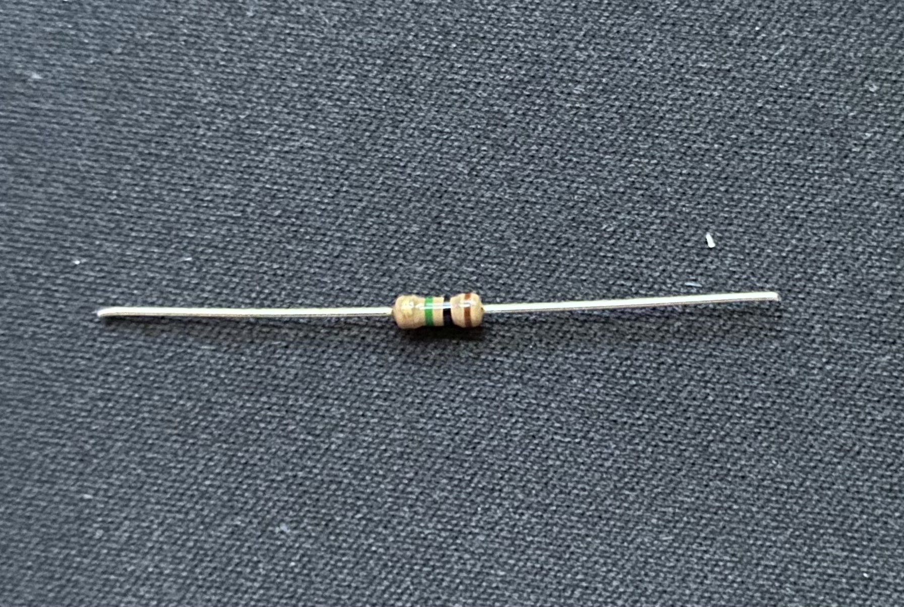
I ran into a problem almost immediately as I did not have the 1 MegaOhm resistors which are required for the piano. I told Dr. Harris this and he was able to get me the amount I needed within 24 hours, and on a side note, he put them in this little paper origami thing which I think is pretty cool, especially compared to a single-use plastic bag.
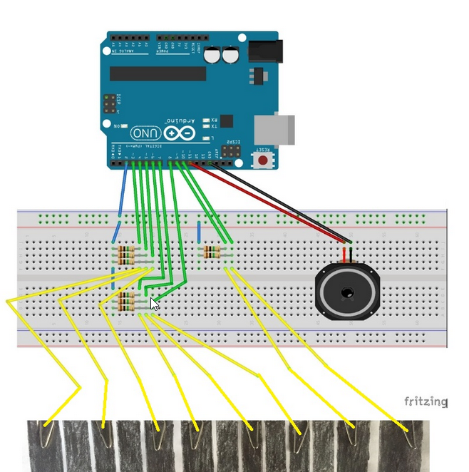
I then ran into a second issue, that being that the schematic I was working off of sucked. The code was full of errors like using a single & symbol in logic statements, and the schematic also had the send pin from the Arduino running to nothing. I had to find a new source for the same project. I found this post doing the same thing, with better code and instructions.
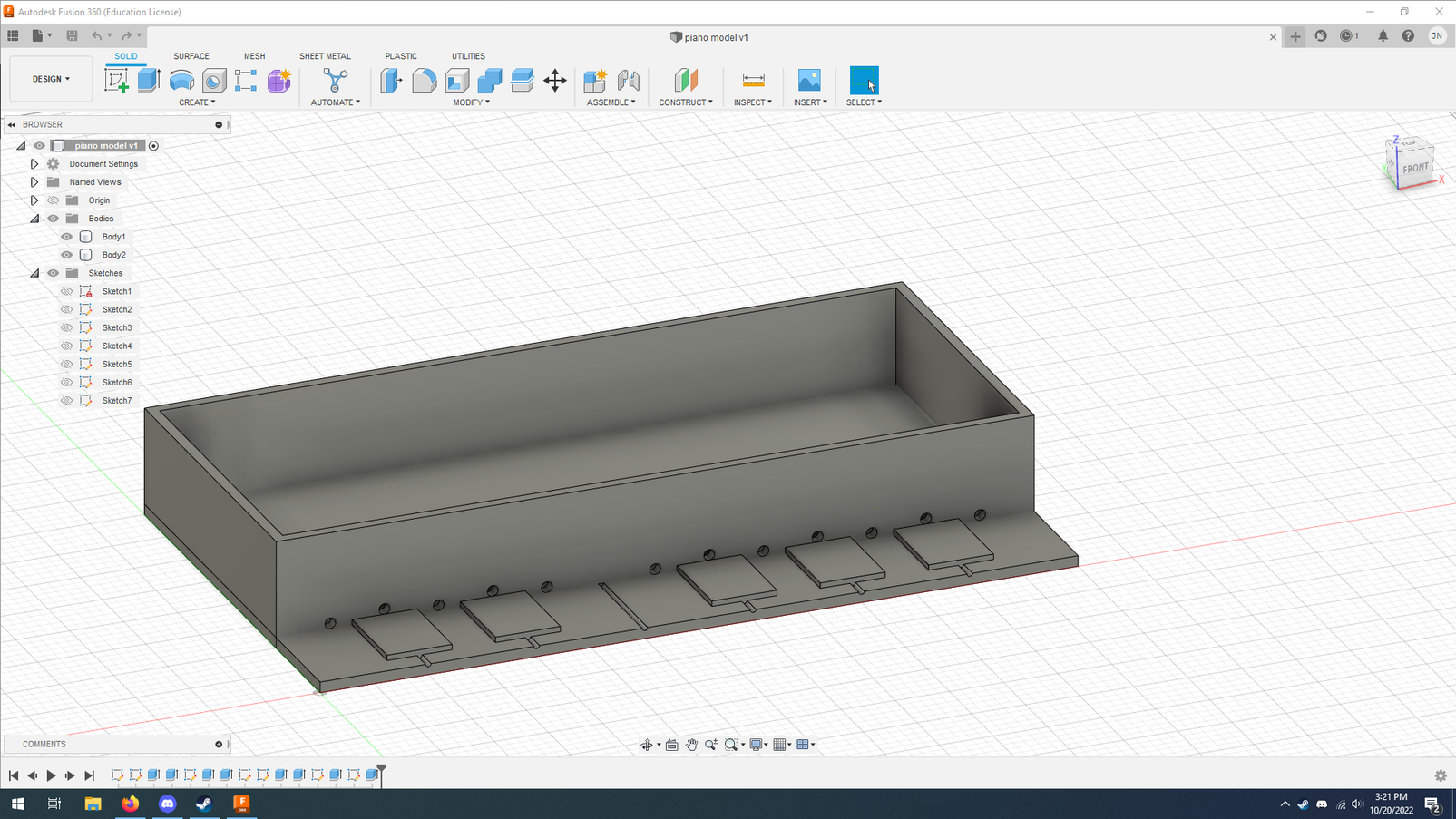
At this point, I shifted gears and went to design the piano. This was my first draft, and if you cannot tell, there are not enough keys for a full key. I put holes in the front of the hollow area to feed the wires through. This was just a rough draft, it did not have the hole for the dial or nearly enough space for the hardware it was intended to hold.
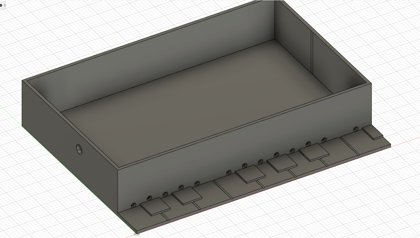
So I went back and made a few tweaks to my original design. I added a hole for the dial, made the holes for the wires bigger, increased the size of the back compartment, and added the missing key. I then 3D printed this, which took 9 hours, and I noticed a few flaws.

The hole I made for the dial was too low and therefore unusable. The flat/sharp keys were too long and made it hard to press the keys between them. I revised these issues, resulting in what I used in my final product.
At this point, I had to go back to making the hardware and code. The capacitive touch sensors work by reading the change in capacitance, or the ability to store electric charge. Now I do not really know how the code behind this works, it just does.
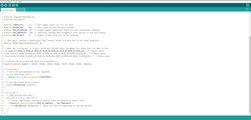
I started with this code and built a small part of the piano before moving on to the rest. I started with just 3 touch sensors with the intent of adding an if statement that would turn it off, it was a struggle, but I got it to work, and I have linked some of the strange bugs I had with it.
From here I added more keys and revised the code.
From here I added code for 3 choices of keys via a variable potentiometer, also known as a dial. This leads to my final code.
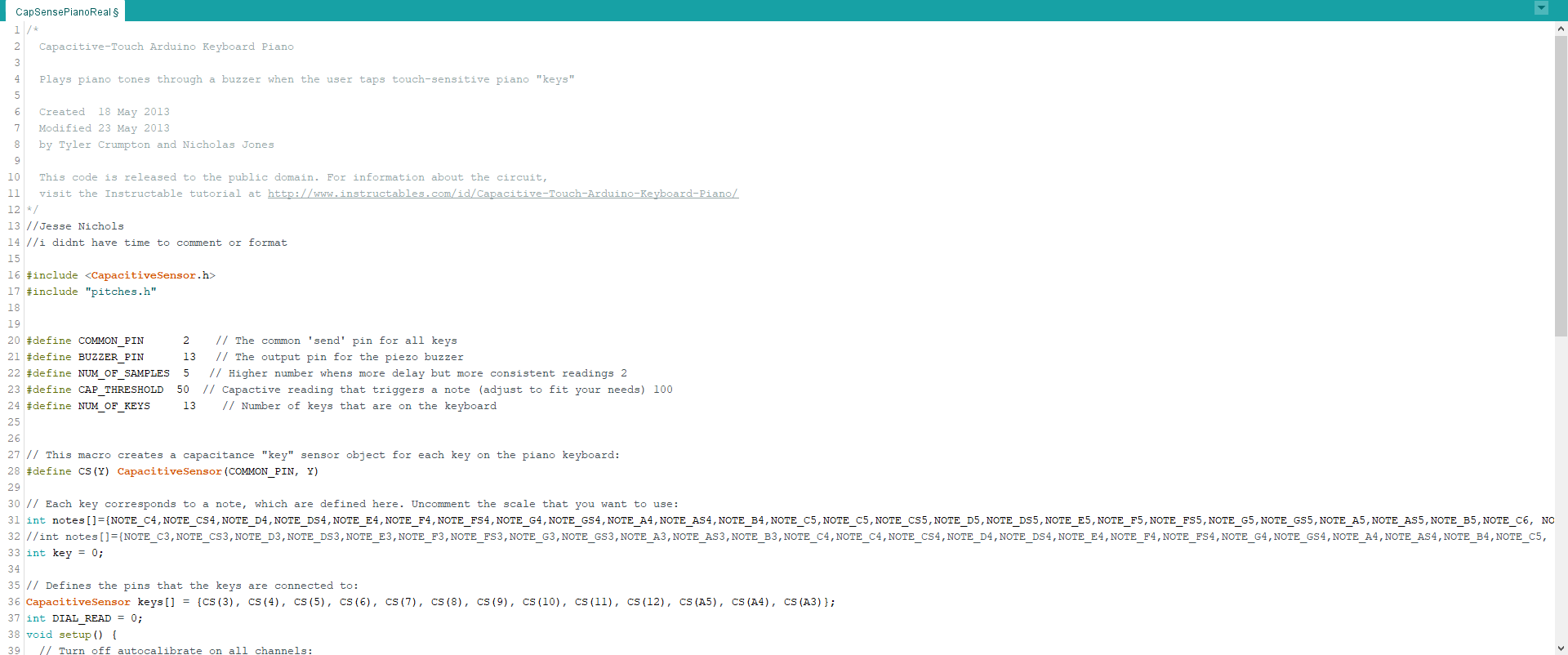
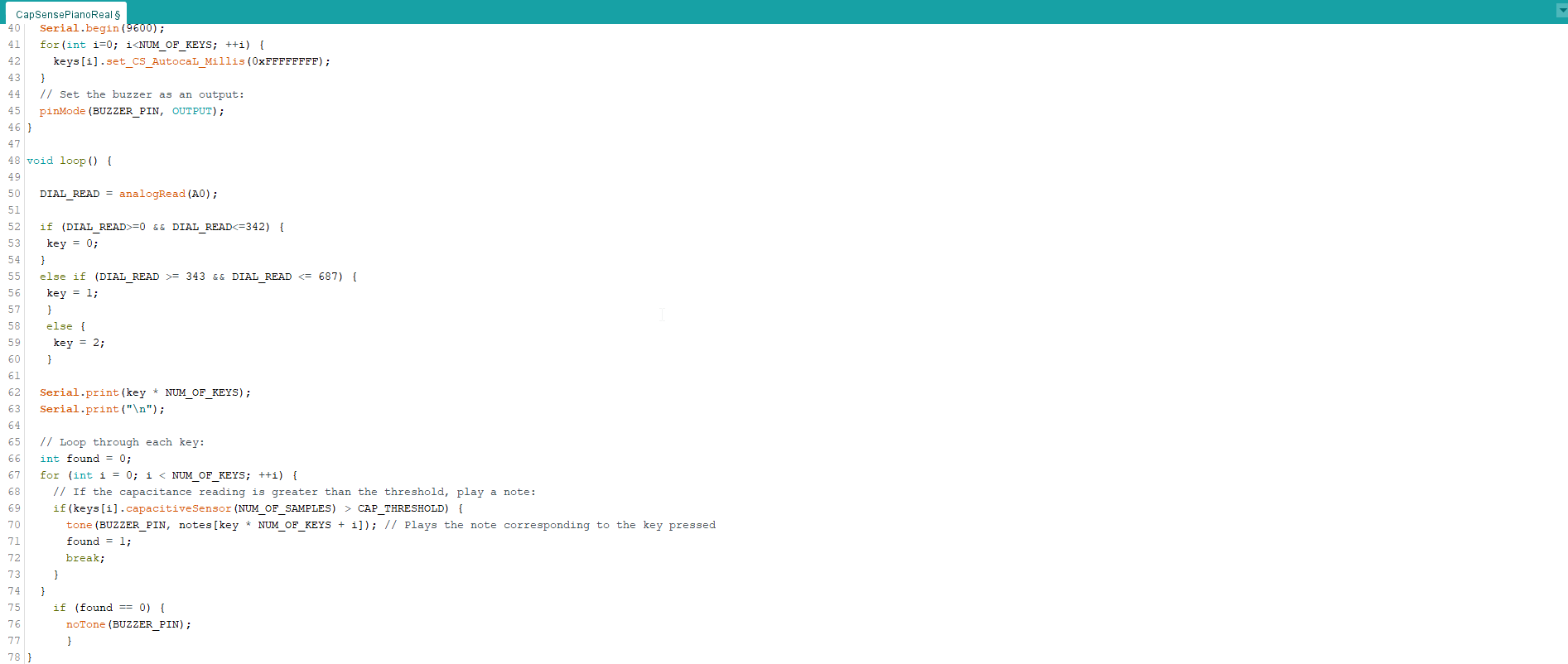
All I added was the DIAL_READ command and the if (found == 0) that makes it quit making noise when nothing is pressed.
I 3D printed a nob for my dial and everything was done.

Now fully assembled it looks something like this.
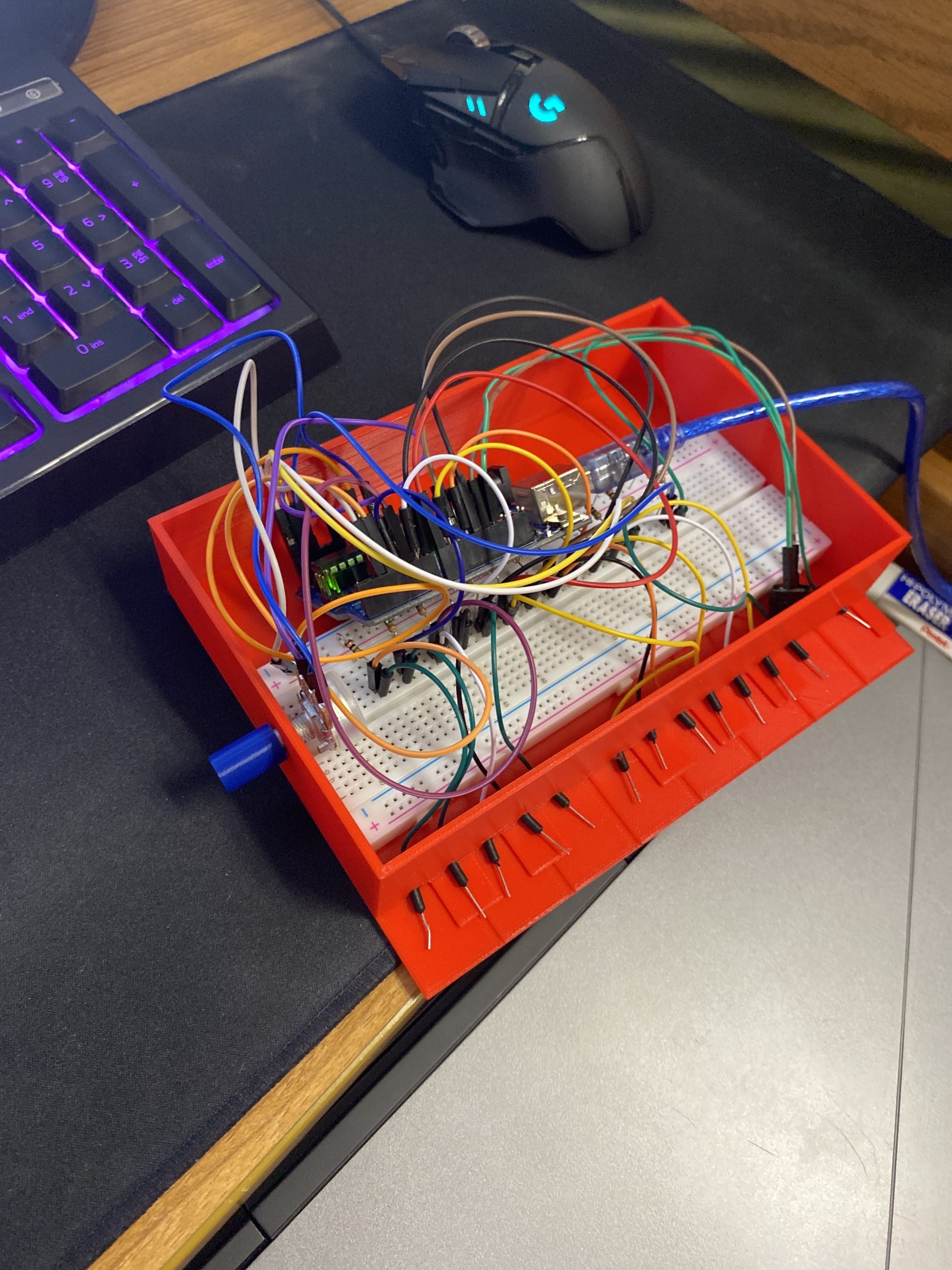
I had intended to use aluminum foil for buttons, but they kept interfering with each other, I also made a lid but it took 8 hours to print and was the wrong size. I would have liked to made the box taller, but that would have been around 10 hours of printing, and I don’t want to hog a printer this late in the semester for a marginal increase in quality.
And it looks like this when working
Recent Comments