For this project, we had to create a robot car that could solve a maze and put out a fire. The maze looked like this. vvv
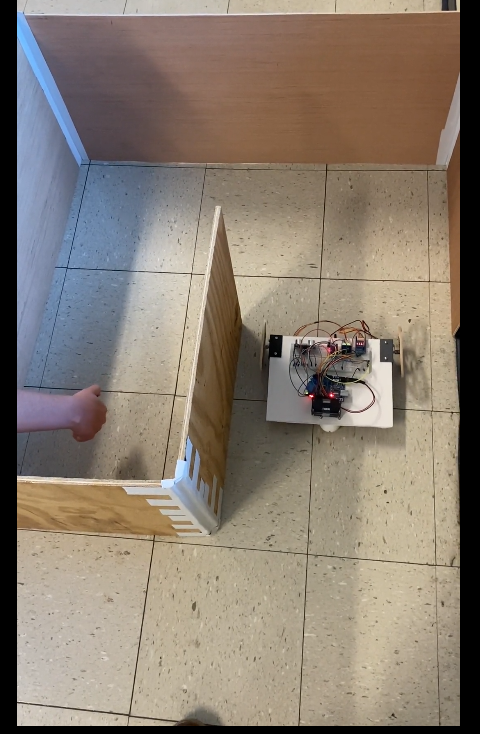
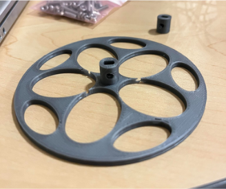
We were supposed to digitally draft and 3D print a few parts, including, the motor mounts, the wheels and their hubs, and a caster wheel. We also had to use an ultrasonic sensor, an IR light sensor, and a relay. We used the feedback from the IR light sensor to tell when there was a flame in front of the robot, from there we signaled to the relay to switch, allowing power to flow to the fan on the robot in order to extinguish the flame. We used the ultrasonic sensor to read the distance from the robot to the wall and turn when it got to it. Our robot used left-hand logic, meaning it turned left whenever there was a wall, this also means that it would get stuck in a loop if there wasn’t a flame in the maze, as it would continue to turn left.
So we began work on the robot. Like I said before, we used simple left-hand logic, nothing fancy. We decided against using a 3D printed baseplate, as if we messed up with the 3D design it would take several hours to reprint, compared to the foam board which is basically instant, it was an obvious choice. Below is a picture of our final robot, and seen here is a video of the robot functioning, please note that the lighter used in this demonstration was, unfortunately, a windproof lighter.

One of the big things we had to iterate was our wheels. First, we had to create hubs that fit securely, this took several attempts to get hubs that fit well. From there, we created the wheels, but my partner and I didn’t communicate well so they were different sizes, one relatively positive thing about that is that there was an issue with my partner’s wheel printing incorrectly, so it already needed to be reprinted. At this point in the wheel process, we hit another roadblock, the holes for the screws on our hubs were too loose, meaning that the wheels were prone to falling off. After much trial and error, I found a solution by adding enough 3D print scrap to the inside of the hubs that it fit securely.
Messed up wheel my solution to the loose wheels

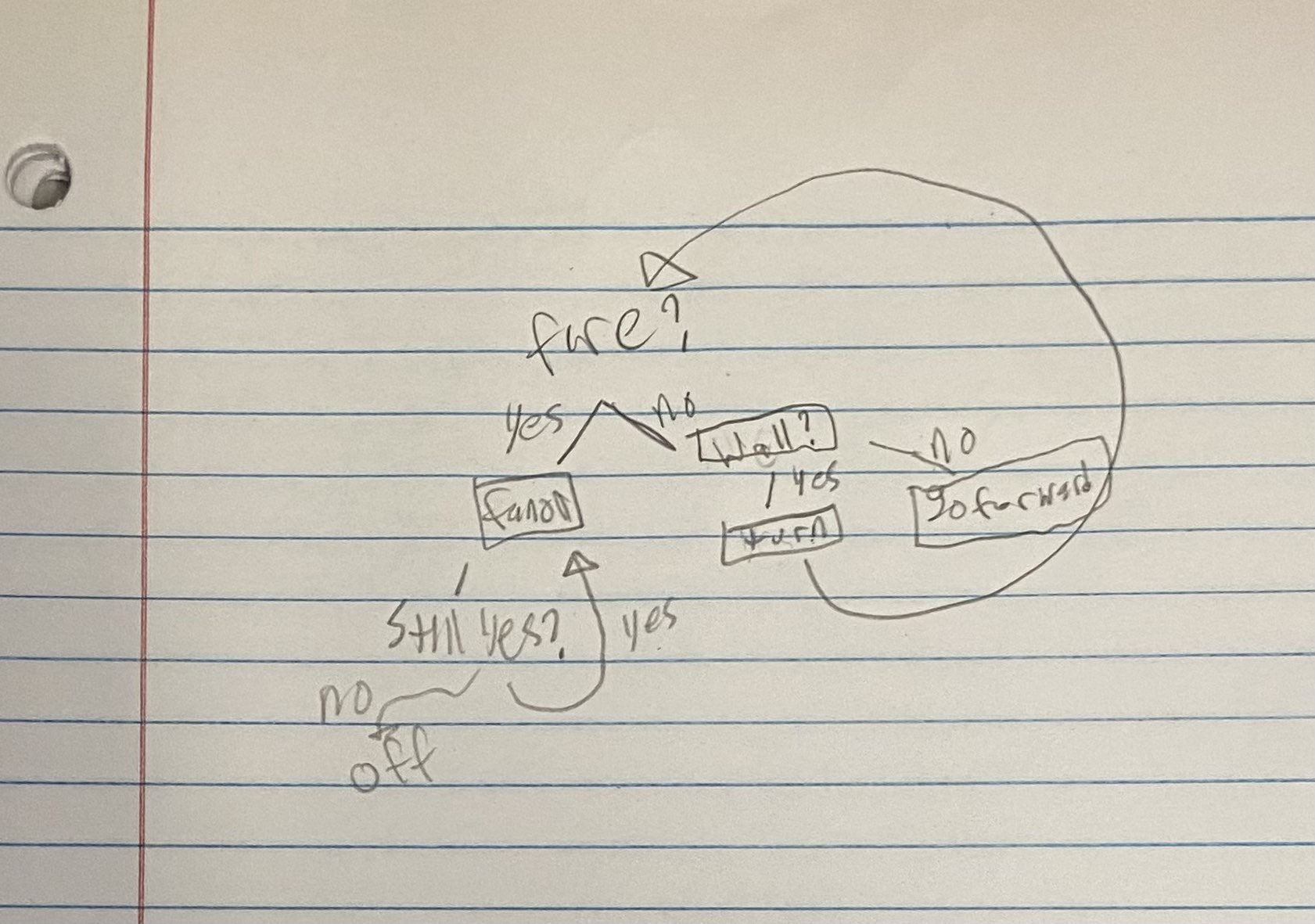
Now onto the coding of the robot. The first thing I learned while trying to create the main code of the robot was that it is really confusing trying to create an external function file in the Arduino IDE, so much so that I opted to not use an external function file. One of the things that we did while programming, which I had never done before, was using a program flow chart. I found that using this chart made coding the robot much easier. It can be seen pictured below. One of the other big issues that I had was that I haven’t programmed in C++ before, I have taken a class that mainly focuses on Matlab, which is honestly a lot easier because you don’t have to remember to put INT in front of stuff or use different precedents for different functions.
I really liked working on this project, there were challenges that I learned from and also places where I had strengths that I could let shine. If I had more time to work on the project, I would have liked to 3D print a body for it, better transfix the parts to the frame, and add better logic to the maze-solving aspect of it. Those are not in order of which I would like to do first. The easiest one to do would be transfixing the parts to the frame with tape, and I know other groups hot glued their rubber bands onto their wheels, which would have saved my team a lot of time putting them back on.
Recent Comments