This is another honors project, this time for ENGR-200, with Professor Spendlove. For this project, I wanted to challenge myself with something that would not typically be in the curriculum of a mechanical engineer, so I went with an AM receiver.
Going into this, I had no experience with designing circuitry or the mechanics of radio receivers. My original goal for this project was much too high, I wanted to design an AM/FM receiver that had an adjustable pickup frequency. I pitched this idea to Prof. Spendlove, and he gave me the ok to start working.
Starting out I needed to learn about how AM receivers work, so I turned to youtube. I did not explicitly look for information on AM radios, but a youtube channel that I like to watch popped up in my feed with a video on AM receivers, this video is linked below with a timestamp where he starts talking about AM radio. This video gives a basic intro to amplitude modulation(AM), demodulation, and amplification, and a basic intro is all that I need as I am a mechanical engineer.
A little later in the semester, I talked to one of my classmates, Liam Pippert, about the project, and his eyes lit up, he told me that he had built an AM receiver and an AM transmitter at his community college. This was great news as I could not find any resources on AM receivers that went past just telling you how to build one. I was a complete novice with working on circuitry so Liam’s help was instrumental in the success of the project. He brought me his old textbook which had a whole chapter on AM receivers, and his old schematics from when he built his receiver. He also informed me that my goals were a bit lofty and that it would be more realistic to shoot for just one frequency to demodulate.
At this point I knew what the stuff did, I just needed the components to build the circuit, so I went to Dr. Yanik for some help. He gave me some more insight into the project, and also informed me of the difficulty of the scope of my project and that I ought to reign it in a bit. He showed me the parts room in the Belk building and how to find the parts I was looking for and sent me on my merry way.
From here, I had the knowledge and resources needed to start building the circuit. I started with the demodulator, which filters out unwanted frequencies and decodes the carrier signal. I had some issues with one of my capacitors being busted, which made my circuit not have resonance with the intended carrier frequency, meaning our output signal was significantly smaller than intended, so small that it could not drive any form of speaker.
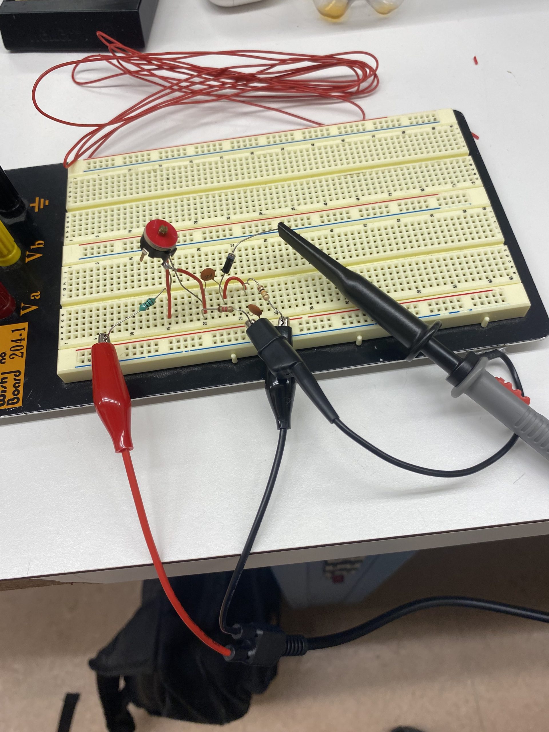
^^^ Demodulating circuit
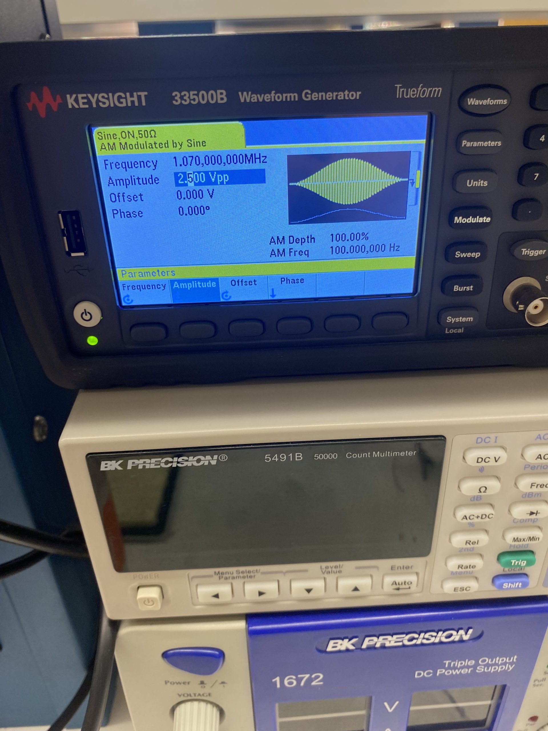
^^^ Waveform generator generating an amplitude-modulated signal
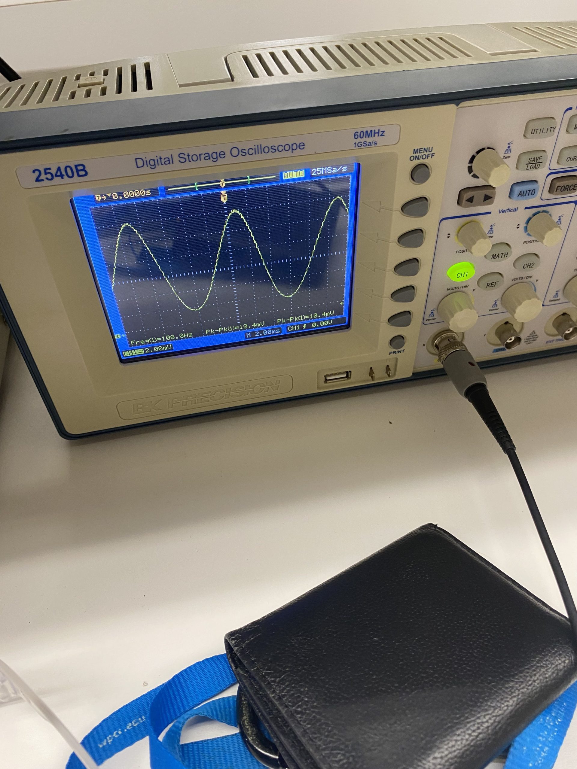
^^^ An oscilloscope reading the output from the demodulator, note that the wave generated by the waveform generator was 2.5Vpp while the one decoded was 10mVpp
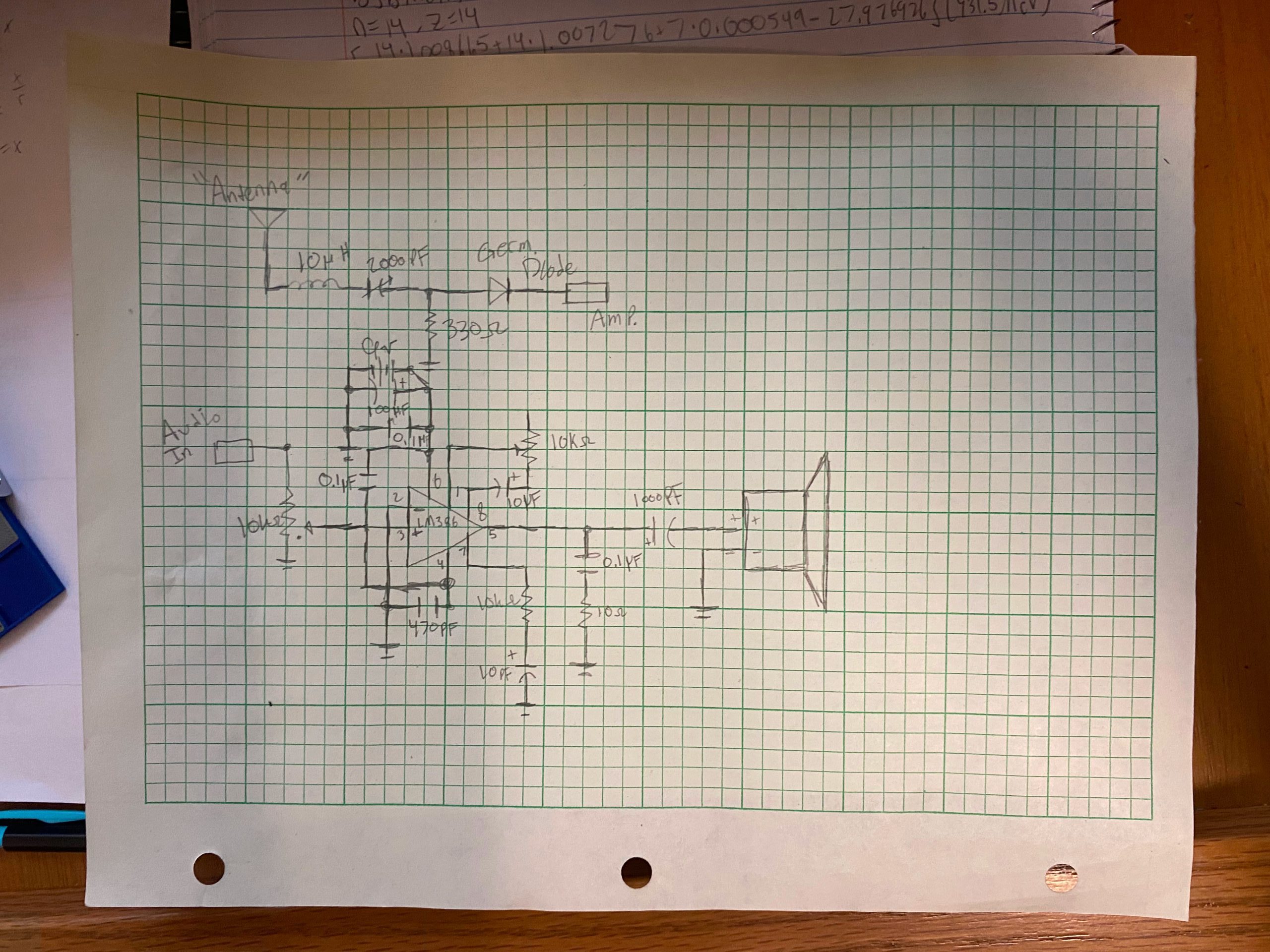
I did not know that the capacitor was busted, so decided to just amplify the signal I was getting. To amplify the signal, I needed to make an amp, the design of which is significantly more complicated than the demodulator. I used a circuit schematic that I found online and borrowed Liam’s LM386 amplifier chip to make the circuit. I used a schematic from circuitbasics.com (https://www.circuitbasics.com/build-a-great-sounding-audio-amplifier-with-bass-boost-from-the-lm386/) and chose to build their “Great Sounding LM386 Audio Amplifier” because the simple one was way too simple.
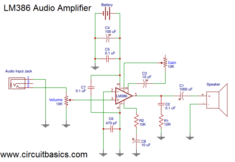
^^ schematic that I used ^^
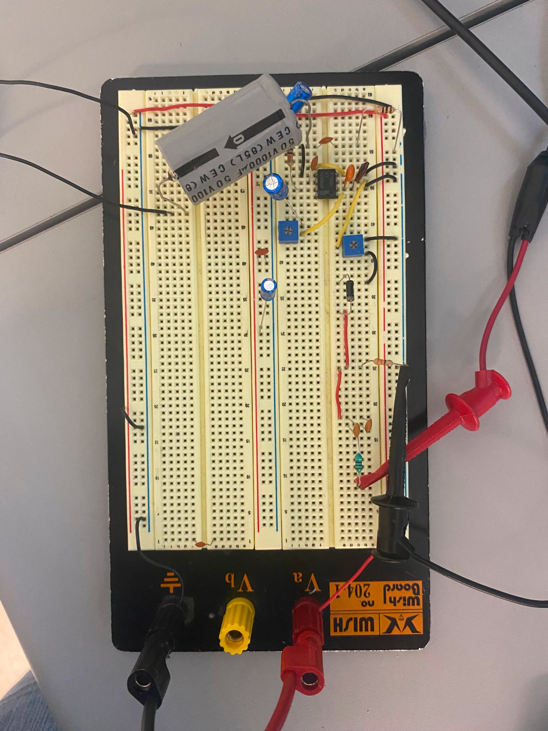
^^ Completed circuit, including the demodulator at the bottom and the amplifier at the top (the speaker is off-screen to the left)
I made a draft of the schematic, which doesn’t look great, but I am not an Electrical Engineer, so that doesn’t matter.
At this point, I also rebuilt the demodulator so that it would have a higher carrier frequency so that I could show off that it only demodulates signals of that frequency. While doing this, I found out that the variable capacitor that I was using was busted, and replaced it with a functional one. After I finished rebuilding it, it was capable of driving a small speaker without an amplifier, but I forgot to take a video of that.
I used an AM generator that was in one of the labs in the Belk building to take music from an iPod and convert that to an AM signal. I also used one of the power supply units to power the amplifier.
Here are a couple of videos of it working, including playing royalty-free music so that I could upload it to youtube.
All in all, I am satisfied with the project, and I am glad I had some reason to use my iPod in a project.
Recent Comments