This project is centered around the design of motor mount for a robot. The design will be simple.
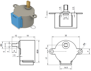
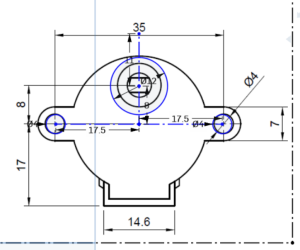
This is the stepper motor that I’ll be using for the robot. The mount will be designed to accommodate this.
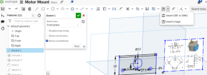
For proper reference, the image of the stepper motor can be imported into OnShape.This is done by selecting the sketch and clicking the import image drop down menu. Select insert image.
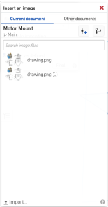
A tab will open. At the bottom left select import.
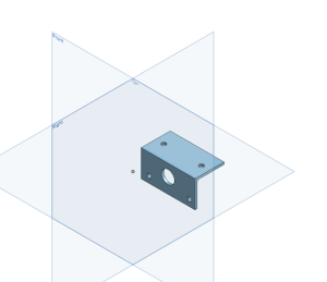
You will be prompted to draw the image on one of the planes. If done properly, this will be your result.
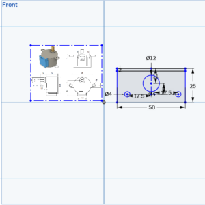
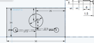
The dimensions of the stepper motor are 50 x 25. This can be successfully drawn by correctly scaling your image in OnShape.
Make all drawn holes coincident with the drawing in OnShape. This should be your result.
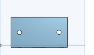
Abiding the dimensions of the object, draw a 50 x 25 rectangle anywhere on the graph. Coordinate intersections will be easiest. Draw a line marking the center of the rectangle.

Make the circles place over the drawing coincident with the center line drawn in the rectangle.
Create a 2mm line from the top of the rectangle. Then draw this line crossing the rectangle.
Extrude the 2mm portion 25mm. Extrude the rest 2mm.
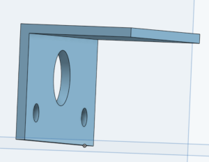
At the intersection of the vertical and horizontal sections place a 2mm filet.
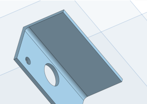
Place holes on the top of the piece. These holes will be the same distance from the side of the piece as their counterparts.
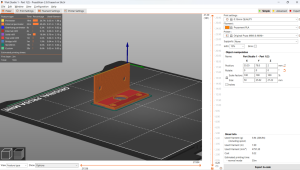
Conclusion:
To 3D print this model, I’ll be using PrusaSlicer software. Standard settings for plastic and the Prusa MINI printer will suffice.
Recent Comments