We were tasked with creating a robot that could solve a simple maze and put out a flame. The maze would have either a left or a right orientation, but could have only two turns. The image below depicts the an orientation of the maze.
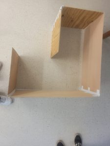
Students were expected to 3D print any necessary parts that were not provided. This included items such as wheels, component mounts, and caster holder.
My robot design made use of several previous systems that exist on this blog. This includes wheels and hubs, flame sensors and fans, and ultrasonic sensors. The overall design intention was to bring as many previously designed components together and adjust values as required. This approach limited errors and maximized time.
My approach as well as my partner’s was to create a design that could solve the maze in any orientation by basing its movements off the measurements taken by the ultrasonic sensor mounted on the front. The initial design for this was to have an ultrasonic sensor attached to a servo motor that would then be rotated left and right to take measurements. Although this was partially achieved in the code, it was ultimately scrapped due to it being simpler to rotate the robot itself and take the same measurements.
The creation of the robot was wiring intensive, as such, early iterations of the robot struggled greatly with organization as it was sometimes difficult to tell what wires were controlling what components. This problem was solved by the addition of zip ties being attached to the robot to help organize the wires. The pattern in which they were applied was simple: zip ties were applied to wires in a group; groups were determined by where wires going to and coming from.
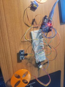
Wires before any organization
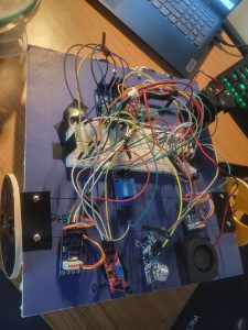
Wires after zip tie applications
Customization was a non-negligible factor of this robot’s design. The picture above displays the emphasis on darker colors. The black and gold wheels were chosen for a stylistic asymmetry. As far as functional customization, the decision to make the robot turn left and turn right to take measurements was determined between me and my partner to both make the code dynamic enough to solve different orientations of the maze and to simplify the code.
The code written for this robot was an educational experience. In this project, I and my partner learned how to correctly used functions, call libraries for components as needed, and to initialize functions. Most importantly, it was necessary for the both of us to learn to correctly write in C++. Early on in the project my partner and I faced many syntax errors. Learning to navigate these was insightful and allowed me to gain a better understanding of C++.
Were I given more time to work on this robot, there were several changes I would have made. First and foremost, I would have spent more time organizing the wiring and placement of components. Even after the application of the zip ties, I still had issues with the organization of wiring. I would have fixed this by using less wires and placing more of the components on the breadboard. Secondly, I would tried to make the rotating servo motor/ultrasonic system work. I believe this would have led to a smoother set of measurements if done correctly. Despite this, I am proud of the work my partner and I were able to accomplish on this project.
Recent Comments