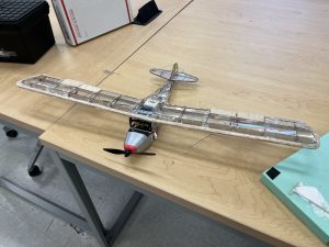
The primary goal is to replicate the Taylorcraft B, which is an aircraft from the golden age of aviation and was introduced in 1938. In our project, our goal was to make and design the plane at 1/15 scale and make it operational from a controller. We will be using small motors, small controllers, and lightweight material as the main body. When selecting a plane, we were given different planes from the 1930s-1950s, while not knowing the tools and supplies we have for the aircraft, we decided to go for a plane that is more simple and can handle higher winds speeds while flying since we know that that even though all of these aircraft are expected to fly and handle normal wind and normal weather conditions understanding the weather in Cullowhee is important. The rain in Cullowhee has 4.8% more than Raleigh. Which, when it rains, it usually caused by low pressure systems and will bring higher winds to the area as a subfactor of the rain. Now understanding this, we can conclude there will be a higher chance of unstable weather conditions during our test,t and as it is expected to compete in a rally system against other planes from other students in our class. While looking at aircraft to model on other planes that were options had a low dihedral angle from the wing, which can cause several benefits, but the main one being able to maneuver in a small area. while that is important, the location we will be doing our rally isn’t optical,l rather more like a track area that is just two curves and straight lines. Now considering that, having a higher dihedral angle will be important to increase in lateral stability, which can help us to handle harder wind gusts and handle the different weather conditions from the location we will be at during the flight. Unlike other aircraft option given our aircraft is a high wing aircraft which will increase our stability while flying since our center of gravity is below the wing which will give us more room to play with on where we will put our eletronics int eh inside. another benefit of having our plane is we have support beams which can help carrying the weight since it will also have some of the weight of the fuselage onto the individual spars and distributing the weight more evenly onto the wing and decress the amount of stress on individual parts and apply less load to each parts rather than just having all the load be on individual parts.
4 roles will be important for the plane, and each group will have four students and collaborate to share thoughts and ideas on how to bring the plane to life. The 4 roles are Wing teammate (which will be the wing lead and leader of the group or referred to later as wing lead), Fuselage teammate, Integration teammate, Electronics teammate. During the team selection, the main students who will be given the Wing and fuselage are usually mechanical engineers and civil engineers for their concentration, since it would be good to have a basic understanding of fluids and how structural integrity is important when modeling an aircraft. In the beginning, I was given the role of Wing Teammate since I was the only mechanical engineer and I have experience with team management and leading a team with hard deliverables from my experience at RTX, and I was up for it.
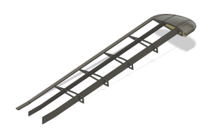
The byproducts of the wing were the model shown with the ribs and spars inside. The model was drawn using Fusion 360 and different methods to create the Rib and Airfoil, which varied since different parts had to take into consideration the construction of the wing. The ribs and spars will be using light weight wood and be Laser cut as part of the fabrication, so standard dimensions are necessary to transfer it onto the laser cutter while also not producing a part too small where the laser cutter will just have the part fall out. The Wing skin was used by lofts and different drawings from different Taylorcraft B and different aircraft planes, taking some from the actual repair book of the Taylorcraft and some from smaller-made models of the aircraft, which caused us having to get different scaling factors when creating the wings and fuselage to integrate. The Leading edge will be made out of a solid piece of wood that will fit and need to be sanded to the wing model, but is taken into consideration when making the ribs, which are already cut out of the rib so it fits in the wing. The skin of the plane will be made out of a moldable wrap-like material based on
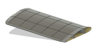
the information given by the professor. The wing tip is constructed of 5 different components to make a smooth rounded raper wing tip like in the original taylor craft model. The wing tip more than likely will be altered based on the available tools and weight of the vehicle. The ribs of the plane also already have cutouts to provide space for electrical components to be integrated, and also to reduce weight while also maintaining enough structure to handle the winds and maintain the wings built together against the forces that will be applied to the wing. The actual Taylorcraft had 14 ribs on each wing, and the reasoning was the already light weight design of the plane. The calculated maximum weight for the aircraft based on the motors we were provided was 100 grams so lowering the parts amount while also providing structural integrity is important. We decided to reduce the amount of ribs to 6 on each since it is distributed evenly on 6 different parts of the wing. and knowing that the wing will be having support beams is reassuring that making us only have 6 ribs can be effective since the weight will only be on the spars, but also onto the ribs.