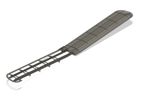
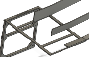
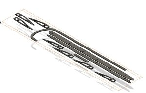
The wing is crusial for gettign lift having eading edge, trailing edge, spars, rib and ailerons for the current class we where only required to model the spars ribs trailing arms railing edge and leading edge on cad the red would be made in person since the available materials where still not known for the time being this was the result of the CAD model
The next step would ensure the wing tip and wing are as close as the original plane so using plans and repair manuals form the original plane and small craft planes replicating the plane we took all of the best qualities from the models to ensure a safe and usable wing while undergoing the fitment since the skin of the plane would be wrapped around we only needed to have a general point of measurement for the tracing of the leading and trailing edge
The next step on the aircraft project is to get all of the parts ready for fabrication while creating the spars, trailing edge, and ribs the other step to consider for fabrication is assembling. Thing to consider is how the wing will connect with the plane while other planes will be using a mid wing or low wing we will be using a top wing on our plane since our plane we are designing off of is a top wing and so making the connecting between both the wings halves and the fuselage was crucial for the plane to operate.
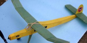
While considering the wind condition the plane can deal with the next and only issue being how to connect the wing and the fuselage while also maintaining a strong connection and finding a way to connect them both without glue being the main way of connection. I looked into how RC planes top wing work and how they have been manufactured to be assembled with the common way being a elastic hold or a hook to latch onto the plane or an elastic form that wraps around the plane as shown in the example and seems to be a popular option. while it is practical and reusable and makes its accessible the only con to this woud be the amount of load the band will have to deal with which will cause ti to have a constant load from the wing to the fuselage cause of the lifting force.

The next option that was popular was the Rod/Tooth method that was used for multiple more professional grade planes. the pros to this option was it would handle more loads evenly, more rigid, reusable and practical which the only main con is how available it is compared to a rubber band we would be able to 3d print this option so the con isn’t that severe as if we where a DIY personal project. The next con is having the wing lead and the fuselage role to work together to properly integrate this option and for both to have a basic understanding of loads and how the load will be put not just onto the wing but also the fuselage where it will connect to. luckily all both the fuselage and wing are done by me and modeled by me so one of those are good enough. while the other issue being having a basic understanding of wind loads I was did end up researching how the forces will act on the wing and fuselage when integrated which I will go into more detail later. the next part will be how to integrate this part for fabrication and get the top frame ready as well as the spars since it will be needed to be modified for our part. The part that connected everything together will be 3d printed and the rest of the wing and fuselage will be laser cut reason being the 3d printed part will undergo most of the stress and will need to be more rigid and heavy duty while the spars will have a cable to help them undergo the lifting force so no so much focus on that.
I decided to make a hook like system to ensure that the plane will be able to hold its own wing and interact with the fuselage. since I am now in the role of fuselage I’ve been able to make a way to making a latching like system that will hold the wing onto the fuselage. while the primary ways on how to attach the wing to the fuselage was not thought I had to take into consideration since the only time the professor did was really only open to students who have a mid or low wing and so we had to make a part that a 3d printed centerline rib that will interlock with the spars and lock into plane with the top frame of the plane.
By doing this we would have to add some type of bar for this part to be made with so it can operate underload and locks with the plane while also keeping the parts of the wing together. the next part that was having to think was where we wanted the tress to be on when holding the wing since we understand that the load will be onto the spars we put the bar ahead of the first spar so it can hold most of the load coming front he wind since the wind will be wanting to lift up the wing which leads to the plane under going load coming up and pulling the top frame of the fuselage.
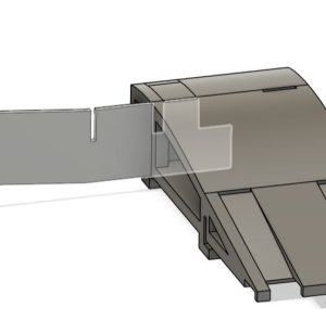
The next bar where the 3d printed part would interlock will be put behind the back spar since it will be doing under less lifting load we want the back to be behind the spar so it can undergoes the load coming from the pitching movement and the rolling movement since we would not want the load to only be on the front bar since it can lead to uneven loads and since it is already thin material leading to cracking and fracture point.
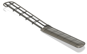
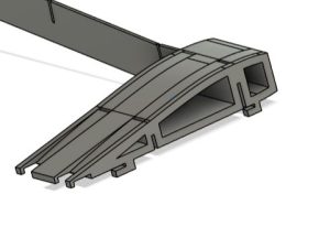
The plane is split in half for manufacturing reasons, this will lead to us having to change how one of the trailing edges are made so instead of 4 trailing edges it will be turned into 3 with the middle 20 combining so it interlinked with the 3d printed part. which is shown to the left which should interlock with spar 1 and spar 2 on each side so it can hold onto the middle both sides of the wing and then interlock with the 3d printed part and hold tis self under load. The heaviest part of the wing that isn’t electronics will likely be the wing mounting to ensure the wing and fuselage connect to each other.
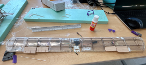
 The next the final part of this section of the project will be the fabrication since we will be using a laser cutter I went ahead and set the spars ribs and trailing edge to the plane so it can be ready for laser cut. a part that was taken into consideration is the weights that will be put onto the basswood so we can ensure the cuts are even and the sheet doesn’t bend during the cut we will be putting weighs on the sheet and start the laser cut that way. The updated cut sheet is shown on the left and now ensures we have two extra ribs and will be 2 cut sheets since we want to make sure we don’t go over a curtain amount of cut sheets just incase we need to recut any parts since the prototype might need some changed over time or even the laser cut might make an error.
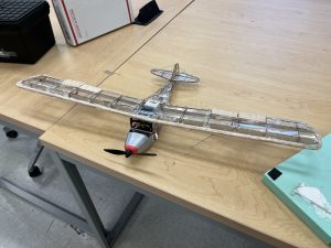
Getting things cut and bridging everything together was a hassle, but got finalized, ensuring the electronics fit and the fitment was correct the final wing got assembled and blued together while using mylar from Australia we got it glued together and esnured the wing would be flight ready. these are the photos of the wing assembled together and on the fuselage body.