At the beginning of the semester, each of the students within my class were told that by the end of said semester, we should be able to construct a Fire Fighting Robot. This would entail making the bot fully autonomous, programming it to where it can navigate a small maze, and then finally extinguish a flame at the end. So, my partner Fernando and I, set out to complete this robot. He handled most of the coding aspect of the robot, while I handled the construction and setup. Here is my partner Fernando’s blog post on the code of the robot.
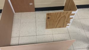
Here is a picture of the maze that the robot had to navigate through:
Also, my partner Fernando covered the code aspect, but I did learn to program the Flame Sensor and Relay, and the Ultrasonic Sensor. The links to those are below:
| <Flame Sensor and Relay> | <Ultrasonic Sensor> |
For the Flame Sensor and Relay, I programmed the sensor to pick up a flame or Infra-red light to activate the Relay; and for the Ultrasonic Sensor, I programmed it to detect an object at a certain distance in front of it, make it turn a micro servo 180 degrees when said object is detected, and back when the object is removed.
__________ __________ __________ __________ __________ __________ __________ __________ __________ __________ __________ __________
Since I handled the construction of the robot, I decided the best course of action was to create the chassis for the bot, Design, import, and 3D-print components necessary, Attach components and Arduino hardware to framework, and Provide a portable power supply thus making it fully autonomous. Now, I would like to lay out the iterations and the process of each component. (I will link a post about a component if there is one)
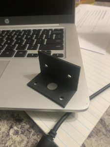
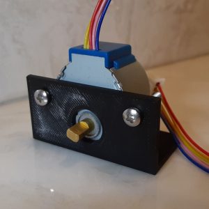
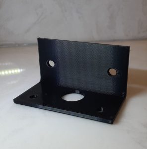
1. Motor Mount: With the Motor Mounts, we had zero trouble with this component. They printed perfectly the first time through, and they didn’t snap when stress testing and mounting.
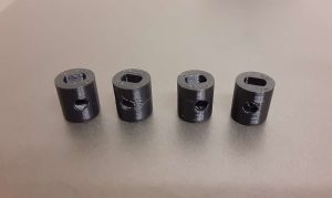
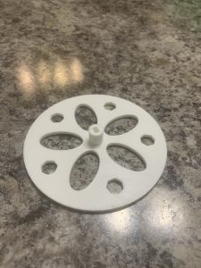
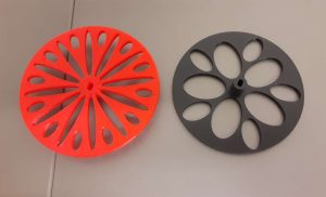
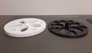
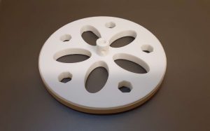
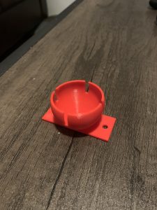
2. Hubs and Wheels: This is where most of the problems and iterations occurred. The hubs printed well enough, and fit the Stepper Motor. However, for some reason, my partner and I had the same measurements for the hub, but his screw holes were to small, and the opening for the axel was too big after the print for some odd reason. But once that was figured out, we printed our wheels. Unfortunately we didn’t escape any issues for this print either. The wheels printed well for the first batch, the only problem with them was that they were too thin for the rubber band tires to properly stay on. So, I came up with the solution of thickening the Wheels for 3mm thick to 7mm thick, this way the rubber band tires’ width was smaller than the thickness of the wheel. Also we printed a Ping Pong Ball Holder, which actually didn’t have any issues and printed first try.
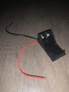
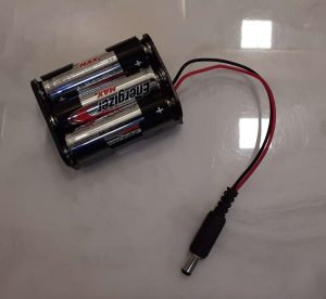
3. Battery Pack Change: For the project I hade to de-solder a plug from a 9-volt battery pack, and then re-solder it back onto a AA battery pack. Not many issues during this procedure, other than burning my hand an excessive amount of times because I wasn’t paying attention to where my hand was. (I will be working on that down the road, staying out of accidents like that I mean)
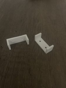
4. The Failed Idea: I had an to secure the Bread Board to the chassis, so I designed some mounts in Onshape. I couldn’t find the proper measuring equipment for the dimensioning, so I ended up just estimating a little bit. Turns out, that was a mistake because they came out too small, learned my lesson there, really quick. However, I ended up mending my blunder by getting the idea to secure the Bread Board and Battery Pack by put a couple of more screws in optimal places on the chassis.
__________ __________ __________ __________ __________ __________ __________ __________ __________ __________ __________ __________
Now I would like to talk about the things that I learned from this project, and the things that I would have like to improve if I had the time.
For the things that I learned, I further fine tuned my skills in 3D printing, because i used to do it a lot back in high school for a couple of Drafting classes. Also, I learned that slicer G-code does not translate across different models of printers very well. Lastly, as mentioned before, I learned the trying to estimate your measurements will almost never work out for you, unless you get really lucky of course
For the things that I would’ve liked to improve upon, if I were to have more time with this project. I would’ve liked to develop a more compact and efficient design for the robot as a whole. I also would have liked to have been able to secure all the components to the chassis a bit more.
__________ __________ __________ __________ __________ __________ __________ __________ __________ __________ __________ __________
Now lastly, for the finished product:
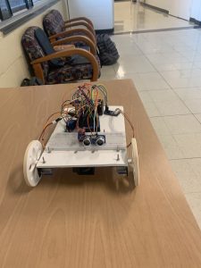
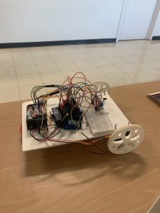
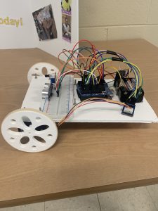
The only changes that I made past this point was that I cut off the back corners of the chassis so it didn’t run into the wall, and I attached the fan below the chassis so it did not block either of the sensors. That was pretty much a last minute thing though. Overall though I am actually very proud of the finished product.
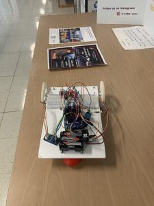
Here are some successful test of the robot going through the maze, just to prove that it works:
Once again, I am all around happy about the things I learned and the finished product, and I’m excited to do future projects.
Recent Comments