Design Process
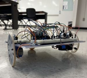
My partner and I were tasked with building and coding a robot that would solve a maze and put out a flame. The finished robot is shown in the image above.
Motor Mount & Wheels

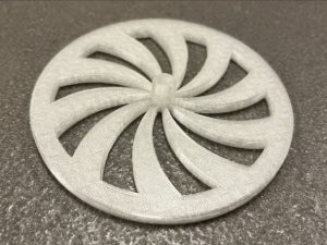

Both my partner and I had to draw, and print, a mount that would secure a stepper motor onto our robot. It is shown in the first photo, both are similar in appearance. We were also tasked with designing a wheel the would attach to the stepper motor. They are shown in images two and three. The wheels had to be the same diameter or the robot would not drive straight. This meant we had to make sure our wheel were similar. The same goes for the motor mounts, if they were too different it could make the robot drive crooked.
Wiring the Robot

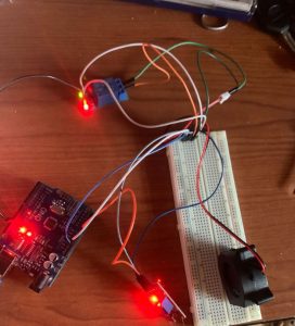
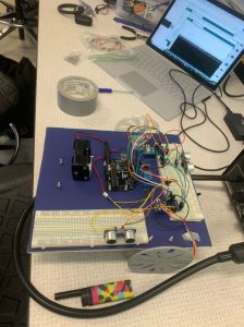
The first image shows the stepper motors wired together on a breadboard. The second image shows the flame sensor and fan wired together on a breadboard as well. The third photo shows the robot fully wired together. We accidently wired the flame sensor backwards so it acted weird for a while. After we sorted it out though, it worked just fine.
Ultrasonic Sensor


In class we were taught how to use one sensor with the example code. On the robot we used two sensors. This meant we needed to either make another copy of the example code and change the values, or we could turn it into a function. we opted for the latter to make the program more efficient. The side sensor, shown in the first image, measures the distance to the right of the robot. The front sensor, shown in the second image, measures the distance in front of the robot. Taking both of these measurements into account the robot is able to decide which direction it wants to turn. We were also able to solve both maze’s in similar amounts of time because we used both sensors.
Coding the Robot
Our program consisted of five major functions. The functions purpose were to move forward, turn left, turn right, detect fire, and read the ultrasonic sensors. The first three functions were self-written and all contributed to the movement of the robot. The move forward function would make the right stepper step backwards and the left stepper forwards. The left function would make the robot turn counterclockwise 90 degrees. It would do so by making the right stepper step backwards as well as the left stepper. The right function would make the robot turn clockwise 90 degrees. It would do so by doing the opposite of the left function; by making the left and right stepper step forwards. The Detect Flame function was also self-written. It was used to detect when a flame was near with a UV sensor and in turn would activate a fan. The function appears three times within the program. Once in the loop before the forward function and once again in both turning function. The function for the ultrasonic sensors was a borrowed library. It was used to gather the distance from the wall using both the front and side sensor on the robot.
While programming the robot we ran into a few issues. The major issues arose when we started writing from scratch, and forgot that AnalogRead was needed to activate the flame sensor. That made things difficult for a little bit but was an easy fix once we figured it out. Another issue we ran into was more humorous. The robot would start turning, but it would just keep turning, and turning, and turning. It wouldn’t stop. We checked to make sure the sensors weren’t obstructed, and then went back to check the code. Sure enough, instead of writing 300 it was 3000. Safe to say we would have been there a while. The last major programming issue we had was the robot wouldn’t check for a flame while it was turning. If it sensed a hand or wall before it put out the flame, it would just start turning. Our solution was to start checking for a flame while in the turn loop as well as in the regular loop code. That solved that issue. In the end we were able to program the robot to solve the maze in both directions and put out a flame.
Battery Cartridge
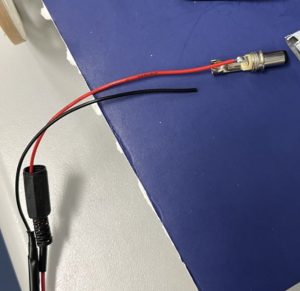
Our robot was acting funny and we figured out it wasn’t getting enough power. Originally, we believed it was the batteries. Then, we discovered that there was 3V dropping across the battery cartridge. We replaced the cartridge and our problem was temporarily solved. The robot started acting funny again. We immediately started replacing batteries, it did not help. We decide to take apart the new cartridge to find that the ground wire was disconnected. It is shown in the image above. We soldered it back into place and the robot began functioning as it should.
Successful Runs

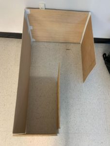
The first image shows the right turn maze. Demonstration.
The second image shows the left turn maze. Demonstration.
Improvements
- Faster – our robot was extremely slow. Given more time we would experiment with higher speeds.
- Better chasse – Our chasse was flimsy and the result was bowed out wheels. It didn’t affect the driving capabilities too much, but it did affect the appearance of the robot
- Wider wheels – The rubber bands kept popping off of the wheels during testing and just in general. If we were to make the robot again we would make the wheels wider to try and prevent this from happening.
- More consistent turns – Most of the time the turns would seem to be 90 degrees, but other times it seemed to be more than 90 degrees. If we had more time I would fine tune the turn more.

Recent Comments