My lab partner and I have been progressively working on building a robot that is designed to travel through a simple maze and then put out a small flame. The robot would have to be capable of locating a wall and being able to turn and navigate through the maze. Then, at the end of the maze there would be a small flame that the robot will have to detect and blow out with a fan. During our time working on this project, my partner and I had to build the body of the robot with some 3D printing elements, wire the robot correctly, and get a working code that would program the robot to do what we wanted. There was a lot of trial and error involved in this process, but we used our failures to continue to improve upon our robot.
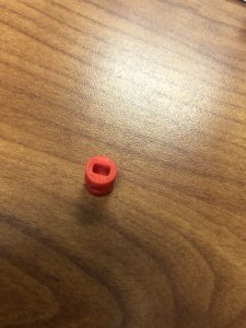
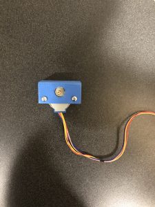
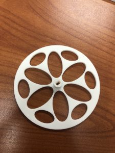
Our first step in building the robot was to get all the parts necessary to build it. As found in earlier posts, we had to 3D print a stepper motor mount for both sides of the robot as well as 3D print two wheels for our robot to drive with. We also had to 3D print a piece that would hold a ping pong ball. My partner created this piece, and we used it for our back wheel. Once, we had all of our parts ready for our robot, we began to assemble the body of the robot. I did the majority of the assembly while my partner would work on writing the code for our robot. To assemble the robot, I used a piece of carboard as the base and screwed all of our plastic elements to the cardboard base. I screwed the motor mounts on the front to corners of our rectangular shaped base and screwed the back wheel piece in the middle of the board at the rear. Pictures of a few of our 3D printed parts are below.
From there my partner and I both began to wire up our system to the Arduino. When we started to wire up our system, it worked well except we couldn’t figure out how to get both wheels to work at the same time. This took quite a while to fix, but after giving different numbers in the code and trying different wires, we found that the stepper motor wasn’t getting enough power. After we found out what the problem was, we switched our wires from the digital pins of the Arduino to the analog pins and it fixed our issue. Apparently, the digital pins that we had one wheel connected to weren’t working properly. However, after all that, we had it all hooked up and wired correctly within a couple of our meeting times.
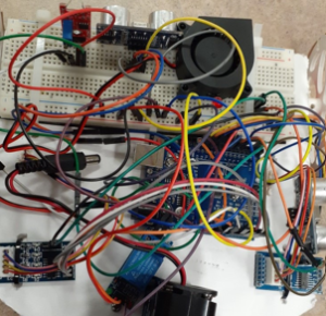
To connect all the wires properly we had to use a breadboard. In our first design we had a breadboard connected in the back and in the front of the robot with our robot’s body shaped as a rectangle. However, for our first test run through the maze we noticed that the rectangular shape of the robot caused it to hit the walls of the maze when it tried to turn. After our first trial, I designed a different style body then what we had originally. With the new body style, I removed the bread board and the rear wheel that we had connected to the back of the robot and cut a rounded back to our robot. I reinstalled the rear wheel but left off the bread board and just connected the wires to the breadboard at the front of the robot. In our second test run we determined that this new body style worked extremely well while navigating through the maze, but we also found another issue we needed to address.
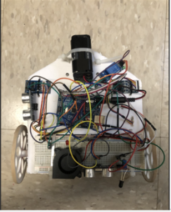
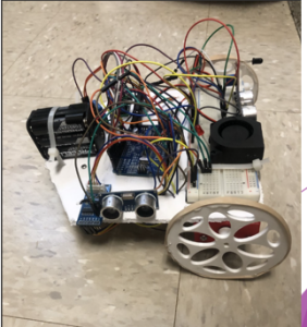
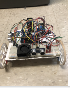
After getting the body to go through the maze like we wanted, we noticed that the robot wouldn’t turn 90 degrees when it located a wall. instead, it would turn a little more than 90 degrees and caused it to side swipe walls and not go through the maze straight like how we wanted. To fix this we had to go to my partners coding. His code ran perfectly, so all we needed to do was make some minor adjustments to our numbers and after some trial and error we finally got our robot to turn about as close to 90 degrees as possible. A picture of our final code is below.
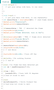
After we got our code working and everything with our body design the way we wanted, our firefighting robot was complete. We did multiple test runs and were happy to see it work exactly how we wanted. If we had more time to work on this project, I would have liked to have designed walls and a roof to our body in order to give it a cool look and cover the wire mess. I would also like to make our robot move faster and perform a type of victory celebration after the robot blew the flame out.
A link to my partners blog, as well as a video of our firefighting robot is below.
Demo Video:
https://www.youtube.com/watch?v=K4-J9IwD7wU&feature=youtu.be
For more information or a deeper understanding of the components involved in this project, please view the previous pages in my blog. You can find the other pages in my blog in the link below.

Recent Comments