In preparation for our final project to design and construct a fire-fighting robot, one of the components that will be used for the robot is a stepper motor to drive the wheels that will be attached to the shaft of the motor. The motor will be attached onto the chassis of the robot using a motor mount that we will design using Onshape, and PrusaSlicer to slice and prepare the model for 3D printing.
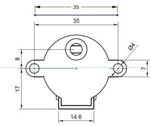
To ensure that our 28BYJ-48 stepper motor will fit onto our 3D printed mount, we have to acquire the dimensions of our motor. Using the internet, I found an image of the stepper motor’s dimensions on www.cookierobotics.com/042. We will save this image onto our computer, and we will be using it the design process.
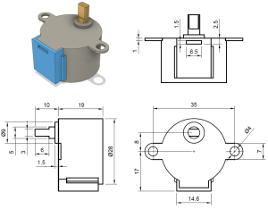
Source: www.cookierobotics.com/042
The first step to build the motor mount, is to open a new document on Onshape. When the workspace opens, we will create a new sketch, and use the front plane of the workspace to place objects and images.
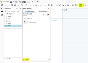
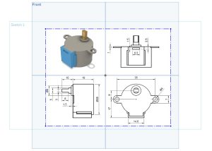
We will now import the image of the stepper motor’s dimensions that we saved onto the workspace. To do this, we navigate to the toolbar on the top of the page and find a tool titled “Insert image”. When you select the tool, a windows opens and prompts you to select an imported image. To import an image, click on the “Import” link on the bottom left corner of the window, and find and select the image you want to use. For this project, I’ll use the image of the stepper motor’s dimensions. When the image is successfully imported, the image will appear on the list in the window. We will click the image and draw a rectangle on our workspace to insert it. The size of the rectangle is not important for now, because it will be adjusted later.
For our motor mount, it will be L-shaped, and will be designed such that one face of the motor mount will contain two holes where two screws can run through and mount the stepper motor onto the motor mount, and a larger hole for the shaft of the motor to come through unobstructed. The other face of the motor mount will contain two holes to attach the motor mount to the rest of the chassis with screws. For these reasons, the base of the motor mount will be built according to the bottom right drawing of the stepper motor dimensions image. Noting that the image containing the dimensions of the stepper motor are in millimeters, Onshape by default uses inches to label length, which is changed to millimeters in the settings.
In the image below, I followed the line that labels the distance between the two mounting holes, which are 35 millimeters apart, and created a line that measures the same measurement.
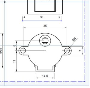
I then move and scale the imported image by attaching a dimension to the image, and changing the dimension little by little so that both lines match as close as possible.
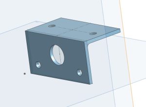
This match enables me to design the rest of the motor mount using the dimensions labeled on the image while being assured the measurements will be accurate. The rest of the model is designed to fit our requirements. The motor mount will be 2 millimeters thick on each face, and will contain a fillet where the two faces meet to reduce the stress on the joint. The final product is shown below.
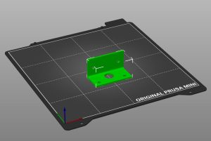
For this project, I chose to use the Prusa MINI to 3D print the motor mount. I export the part as a whole from Onshape, and imported it to PrusaSlicer. In PrusaSlicer, I rotated my model so that the face of the motor mount containing the hole the motor shaft goes through faces down on the print bed. I used the following printer settings:
- Print Settings: 15MM QUALITY
- Filament: Prusament PLA
- Printer: Original Prusa MINI & MINI+
- Infill: 25%
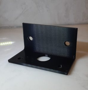
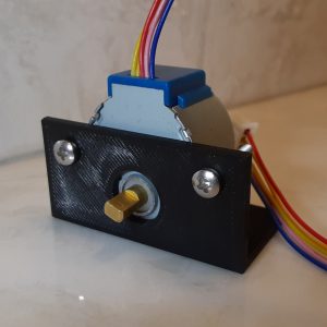
The G-code file that PrusaSlicer provides is then exported to a USB drive, and inserted into the Prusa MINI to start printing. The final product is pictured below with the stepper motor mounted.
Recent Comments