In this project, we will setup UART and data capture between devices by communication between an STM32 microcontroller and an ESP32 using UART, ADC, and I2C. The goal is to read joystick inputs on the STM32, transfer the data to the ESP32, and display the results on a web server interface. By integrating multiple components such as an OLED screen and joystick sensors, we will be able to configure a complete system to showcase the functionality of microcontroller-to-microcontroller communication.
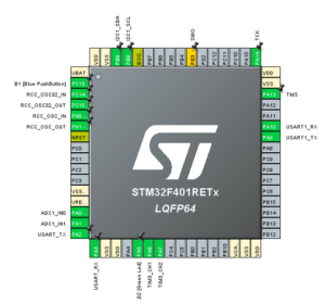
The project begins with configuring the STM32 to handle UART, ADC, and I2C communication. UART1 is enabled using pins PA9 for TX and PA10 for RX, with settings configured to 8N1 (meaning 8 data bits, no parity bits, 1 stop bit) format and a baud rate of 9600 bits/s. ADC1 is used to read joystick inputs from pins PA0 and PA1, while I2C communication is established on PB8 (SCL) and PB9 (SDA) to drive a local OLED screen. These configurations allow the STM32 to collect and format data effectively for transmission to the ESP32.
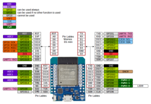
On the ESP32 side, a web server is set up to display data received from the STM32. The ESP32 is configured to connect to a local network by providing a user-defined network ID and password. UART1 is initialized using the Serial1.begin() function, with the same 8N1 format and baud rate as the STM32 to ensure compatibility. Additionally, the default pins for UART1 are reassigned, using GPIO16 for RX and GPIO17 for TX. Proper connections are made between the devices, including connecting the ESP32’s VCC to the STM32’s VIN, setting the STM32 jumper to E5V for external power, and ensuring a shared ground for not only power to the STM32, but to ensure proper UART communication.
The communication flow between the STM32 and ESP32 involves multiple steps. On the STM32 side, the microcontroller waits for an “R” in its receive buffer from the ESP32 using the HAL_UART_Receive() function. Upon receiving this request, ADC polling is initiated to read joystick values, which are then formatted into a string of the form <int1, int2> using sprintf(). This string is sent to the ESP32 via UART while simultaneously being displayed on the OLED screen using the SSD1306 library.
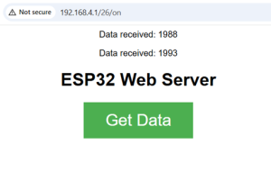
The ESP32, upon receiving the formatted data, processes it to extract the joystick values. A button on the web server interface triggers the transmission of an “R” to the STM32, signaling a data request. When the STM32 responds, the ESP32 checks the UART receive buffer using the Serial1.available() function. The function, recvWithStartEndMarkers(), extracts the data enclosed in < > markers, which is then parsed using the atoi() function. The parsed integer values are converted into strings and displayed on the web server interface using the client.println() function, making the data accessible to the user over the ESP32-based network.
A quick demonstration of this project can be found here: https://youtu.be/-hLyE0hQrU0
Recent Comments