In order to enable our firefighting robot to navigate from point A to point B, we are going to use a pair of stepper motors along with the mounts we 3D printed earlier, which was the topic of a blog post I published earlier. In this blog post, I’m going to discuss the process of designing a hub and wheel for one of the stepper motors, which include the methodology, the reasoning behind design decisions, and the trial and error undertook to reach the final design print.
Our design plan is to get our hub to insert onto the shaft of our stepper motor, a model 28BYJ-48 motor. The hub is going to be held securely to the shaft of the motor by using two 3MM screws, which will be fastened into the sides of the hub to “pinch” the shaft in between the screws. Due to the nature of plastic and its pliability, the 3MM screws will be inserted as slowly and as straight as possible through each hole to “tap” the holes with threads to hold each screw in place, and thus securing the hub to the shaft of the motor with adequate strength. The wheel of the hub will be modeled on top of the hub opposite of the where the shaft inserts into, forming one piece.

28BYJ-48 Stepper Motor, www.components101.com
Referring to the dimensions of the motor shaft, I created the first design using Onshape:
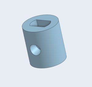
First design model created using Onshape.
The dimensions used for this first design are not strictly following the dimensions of the motor shaft. This is due to the print variations of a 3D printer from model to model. The first design is printed and fitted on the servo motor to check the fitment. This print had a good fit on the servo motor’s shaft, but the holes on each side to fasten screws to firmly secure the hub to the motor were too big for the threads of the screw. This resulted in the screw unable to tap into the plastic hub. In addition, the holes were sitting too high on the hub, and the screws would only partially make contact with the motor’s shaft. The dimensions of the hole to which the stepper motor shaft inserts into are satisfactory, but the diameter of the holes for the screws needed to be adjusted, along with the distance between the top of the hub and the holes.
First design print
To solve this problem, four models were created which were exact copies of the original design, except that the diameter for the holes for the screws were adjusted to be smaller by 0.05 millimeters in diameter for each hub prototype, from 2.95mm to 2.80mm. The position of the holes were also tweaked. All four of these models were 3D printed and assessed for fitment and the ability to be tapped by the screws:
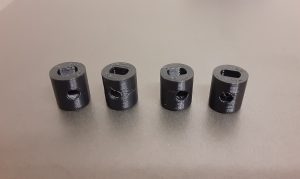
Prototype hubs
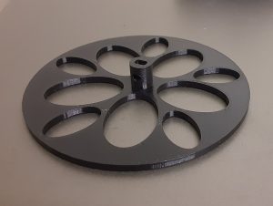
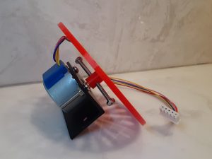
After attempting to tap threads into the holes on each prototype hub, it was determined that a hub with a hole with a diameter of 2.85mm is the best size for a firm fit between the hub and the screws. The change in position of the holes now allowed the screws to have full contact with the shaft of the motor. Having the optimal dimensions for the hub, the wheel portion of the piece is modeled, having a thickness of 3mm, and a diameter of 90mm. This model is then printed as the final design, and mounted onto the servo motor and mount:
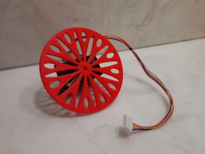
The final hub is 10mm long and 9mm in diameter, with the hole for the motor shaft to insert into shaped to the structure of the shaft with the longest dimension being 5.2mm and the flat sides having a distance of 3.2mm between them. The holes for the screws have a distance of 4.85mm between the center of each hole to the top of the hub facing the motor, and having a diameter of 4.85mm.
Recent Comments